Getting Started with IMI
- 12 Sep 2024
- 14 Minutes to read
- Print
- DarkLight
- PDF
Getting Started with IMI
- Updated on 12 Sep 2024
- 14 Minutes to read
- Print
- DarkLight
- PDF
Article summary
Did you find this summary helpful?
Thank you for your feedback
Introduction to Isolated Management Infrastructure
Isolated Management Infrastructure (IMI) is a specialized framework designed to enhance the security and reliability of managing critical IT assets by segregating the management traffic from the primary business-critical network traffic. This isolation reduces the risk of operational disruptions and security breaches that could affect the core network functions.
IMI operates parallel to your production environment, providing a backdoor for device access in case of an outage.
Key Features of IMI
Security: IMI provides a secure environment by physically and logically separating the management network from the production network. This isolation helps in safeguarding sensitive operations from unauthorized access and potential cyber threats.
Resilience: By decoupling the management tasks from the main network operations, IMI ensures that critical management functions remain operational even if the main network is compromised or experiencing downtime.
Centralized Control: Despite the physical separation, IMI allows for centralized control over all managed devices and systems, offering a holistic view and streamlined management capabilities from a single interface.
Scalability: IMI is designed to be inherently scalable, accommodating the growth of network devices and systems without compromising on performance or security.
Compliance and Best Practices: Adhering to regulatory standards and best practices, IMI helps organizations meet stringent compliance requirements for network management and data protection.
The following image depicts a sample IMI architecture:
Creating a Sample IMI Setup for a Hyperscale Datacenter
To understand how to set up an IMI architecture for a production environment, consider this sample architecture for a hyperscale data center. This example includes two data centers, each equipped with a local coordinator. The local coordinator, an NSR, manages the peers within its site and can support up to 50 peers. NSCP devices act as peers, each capable of managing up to 96 devices.
These devices are connected to a super coordinator located in a different data center. The setup includes two super coordinators, with only one active at any given time to ensure redundancy. This supercluster setup consists of Nodegrid devices deployed in a mesh topology, ensuring high availability and redundancy.
The infrastructure includes both local and remote components connected through various network interfaces, such as fiber and LTE/5G. Below is a pictorial representation of the sample IMI architecture:

Consider Network Paths
Establishing reliable network paths is fundamental to ensuring that all components within the IMI can communicate effectively. Network paths should be meticulously planned to avoid single points of failure and ensure consistent communication.
Define primary and secondary routes for each Nodegrid device.
Configure network interfaces for each connection to ensure redundancy.
Define Network Paths for Reliable Communication
To maintain a resilient IMI, it is essential to define clear and reliable network paths. This involves identifying primary and secondary routes for data to travel between nodes, ensuring that if one path fails, another can seamlessly take over.
Configure primary network connections (e.g., ETH0) for each Nodegrid device.
Set up secondary connections (e.g., LTE) as backups.
Ensure that each connection has its own IP address and configuration.
Define Redundancy and Failover Mechanisms
Redundancy and failover mechanisms are crucial for maintaining network integrity. By configuring multiple network connections and establishing automatic failover protocols, IMI can continue to operate smoothly even when individual components or connections fail.
Enable network failover settings on each Nodegrid device.
Set primary and secondary connections, specifying failover protocols.
Ensure that failover mechanisms are tested and functional.
Verify Path Configurations
Once the network paths and failover mechanisms are configured, it is essential to verify that they function correctly. This involves testing each path and failover scenario to ensure the IMI operates as intended under all conditions.
Conduct simulated failure tests to verify automatic failover.
Monitor network performance to ensure optimal operation.
Regularly test and update failover configurations as needed.
Integrating these elements into the IMI setup allows you to create a resilient and reliable management infrastructure that ensures continuous operation and robust network management.
Detailed Setup and Configuration Guide
Components Overview
This sample Isolated Management Infrastructure (IMI) setup is composed of several key components that work together to provide a secure and efficient management environment.
These components include:
Super-coordinators: Nodegrid Net SR
Local Coordinators: Nodegrid Net SR
Note: You can also use other Nodegrid devices such as NSCP, Nodegrid Gate SR, Nodegrid Hive SR as Coordinators.
Peer: Nodegrid Serial Console Plus
Managed Devices
Temp/Humidity Sensor
Cisco switch
ServerTech PDU
Cluster License
Before you begin, ensure that your Nodegrid NSR and NSCP devices are correctly installed, and it contains the configuration required for this Setup. For more information, refer to the Getting Started Guide for NSR and Getting Started Guide for NSCP.
Setting up a Local Coordinator
Setup Licenses
To enable the full functionality of the Nodegrid cluster, it is essential to apply the necessary licenses. The following steps will guide you through adding cluster licenses to the Nodegrid Coordinator.
Go to System :: License.
Add Cluster Licenses:
Click the Add License button.
Enter the provided cluster license key.
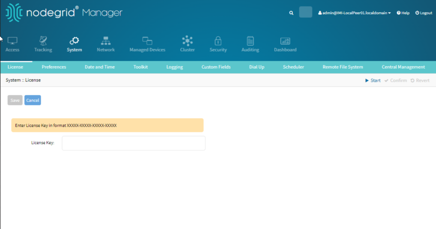
Click Save to apply for the license.

Setup Network Connections
Configuring the network connections is crucial for establishing primary and backup connectivity. This includes setting up Ethernet and LTE connections.
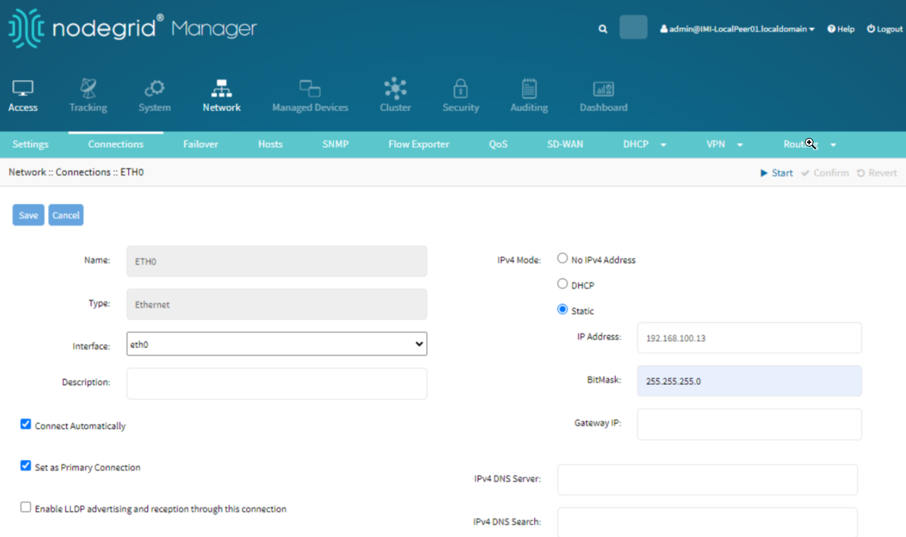
Setup Main Network Connection (ETH0):
Go to Network :: Connections.
Select ETH0.
Set the connection IP Address to <Main-IP-ADDR>.
Mark it as the primary connection.

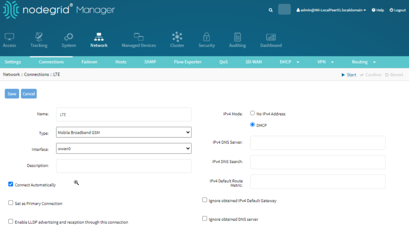
Setup LTE Network Connection
To set up the LTE network connection, perform the following actions:
Go to Network :: Connections.
Select the LTE connection.
Configure the APN settings as provided by your network carrier.

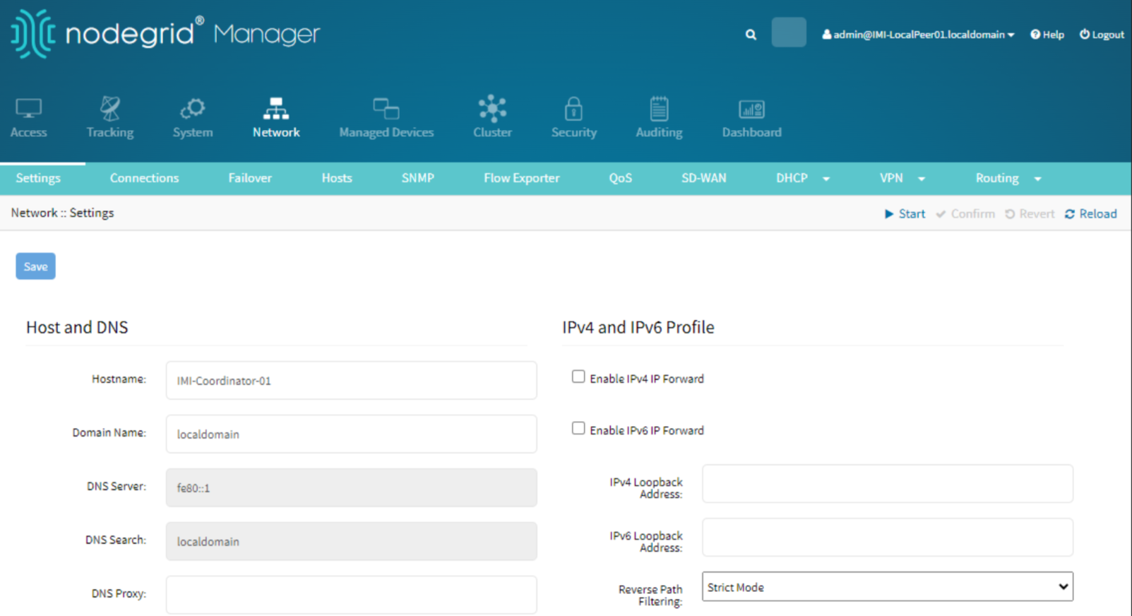
Setup Network Settings
In other Network Configurations, you need to configure the set the hostname and network failover:
Assigning a hostname to the device helps in identifying it within the network.
Go to Network :: Settings.
Set the hostname to IMI-Coordinator-01.

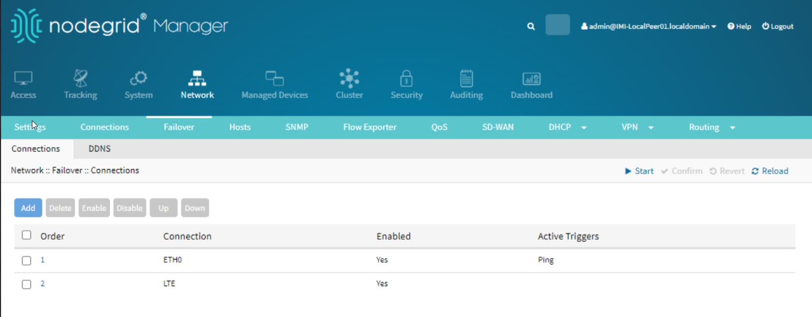
Setup Network Failover
Configuring network failover ensures continuous network availability by switching to a secondary connection if the primary connection fails.
Go to Network :: Failover.
Enable network failover.
Set the primary connection to ETH0.
Add LTE as the secondary connection.

Configuring Firewalls
Configuring firewalls is crucial for securing the network by controlling the traffic allowed to and from your devices. While this setup does not specify any particular addresses to block, it is recommended to talk to your network administrator or consult network security policies for specific rules.
Go to Security :: Firewall in the Nodegrid WebUI.
Add Rules:
Click Add Rule to create a new firewall rule.
Configure the desired rules by specifying the source, destination, ports, and action (allow or block).
Consult Network Security Policies:
Ensure that the rules comply with your organization’s security policies.
Confirm with your network administrator if there are specific addresses or ports that need to be blocked.
Setup Audit Settings
Enabling audit settings allows you to track and record events within the system, providing a detailed log for security and compliance purposes.
Enable File Destination:
Go to Audit > Settings.
Enable File Destination.
Enable ZPE Cloud Events:
Go to Audit :: Events :: Categories.
Enable ZPE Cloud Events to ensure that relevant events are recorded and can be accessed for audit purposes.
Setting Up Authentication Services
Setting up authentication services allows for external authentication mechanisms, such as 2-Factor Authentication (2FA) or Single Sign-On (SSO), to enhance security.
Go to Security :: Authentication in the Nodegrid WebUI.
Add Authentication Server:
Click Add Server.
Select the type of authentication service you wish to add (e.g., 2FA, SSO).
Enter the necessary details such as server address, port, and other required configurations.
Verify with your network administrator if an external authentication server is required and which type to use.
Setting Permissions
Setting user permissions ensures that users have the appropriate access levels and can perform only the actions they are authorized to.
Go to Authorization in the Nodegrid WebUI.
Select the user group for which you want to change permissions.
Change Permissions:
Go to the Profile section.
Adjust the permissions accordingly to ensure users have the appropriate access rights.
Setup Coordinator
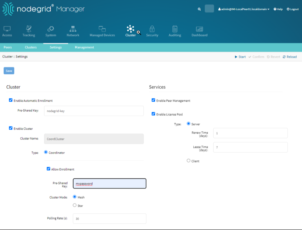
Setting up the cluster configuration for the Coordinator is essential for managing and maintaining the cluster network. This configuration ensures that the Coordinator can manage connected peers effectively, maintain network stability, and provide centralized control.
Navigate to the Cluster tab in the Nodegrid WebUI.
Click on Settings under the Cluster section to access the configuration page. This step takes you to the main interface for configuring cluster settings, where you will set up various options to define the Coordinator's role and manage the cluster.
Check the Enable Cluster box: Enabling the cluster activates the cluster functionality on the Coordinator, allowing it to manage and communicate with other nodes within the network.
Select Coordinator Type: Under the Type section, select Coordinator. This setting designates the device as the main Coordinator, responsible for managing the cluster, overseeing network operations, and ensuring communication between nodes.
Allow Enrollment: Check the Allow Enrollment option. Enabling enrollment allows new peers to join the cluster. This is necessary for adding new nodes to the network and expanding the cluster.
Set a Pre-Shared Key (PSK): Enter a Pre-Shared Key in the Pre-Shared Key field. The Pre-Shared Key is a security measure that ensures only authorized nodes can join the cluster. This key must be shared with all nodes that will join the cluster.
Enable Clustering Access and Peer Management: Check the Enable Clustering Access option.
Check the Enable Peer Management option.
These options enable the Coordinator to manage access permissions for clustering and allow it to handle peer nodes' administrative functions. Enabling peer management allows the Coordinator to oversee the health, status, and configuration of all connected peers
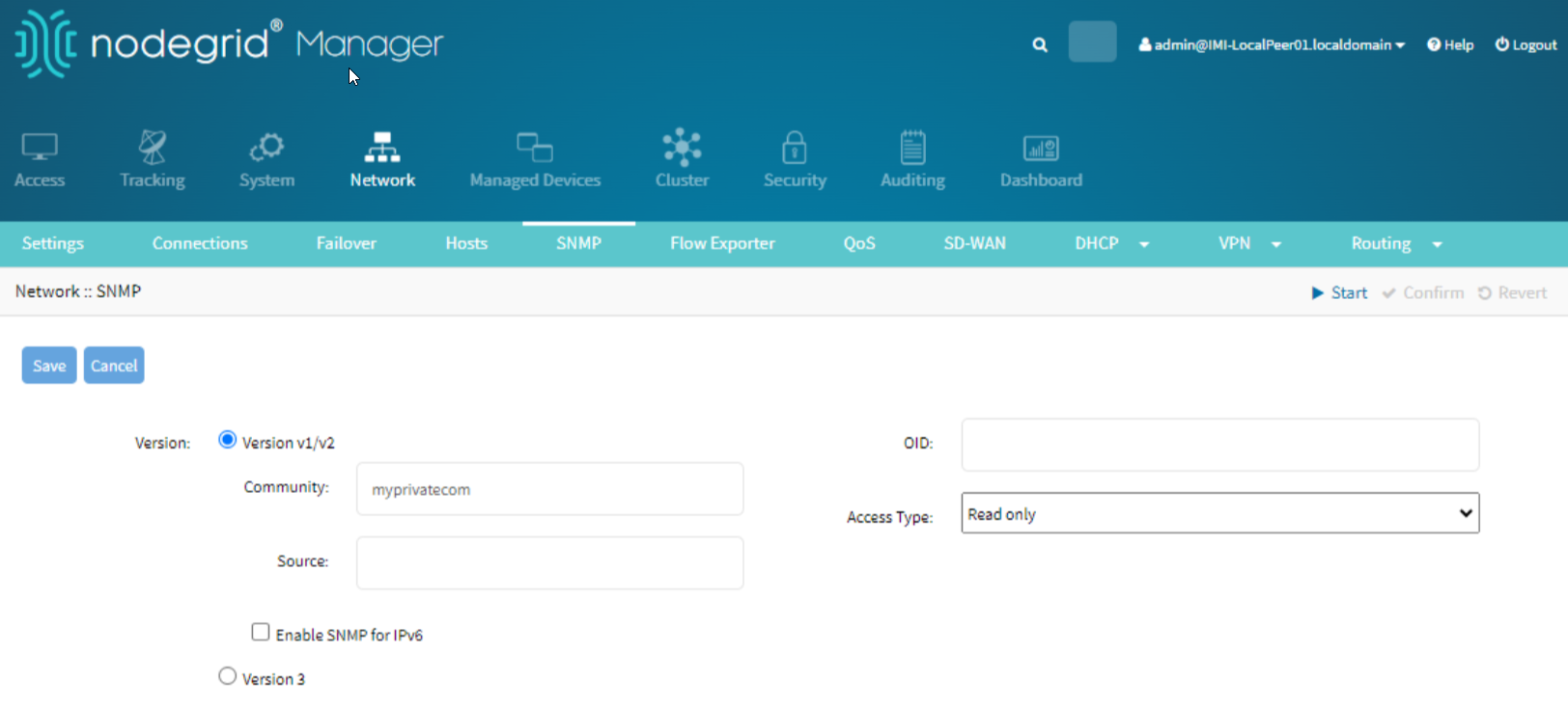
Setup System SNMP Settings
Configuring SNMP (Simple Network Management Protocol) settings is essential for network management and monitoring. SNMP allows network administrators to monitor network performance, detect network faults, and ensure smooth network operations. It enables devices like routers, switches, and servers to send alerts and performance data to a centralized monitoring system.
Navigate to the Network tab in the Nodegrid WebUI.
Click on SNMP under the Network section to access the SNMP configuration page.
This step takes you to the interface where you can configure SNMP settings to monitor your network devices.
Click the Add Community button. Adding a community string is crucial as it acts like a password to control access to the SNMP data. Community strings are used to define what data can be viewed or altered.
Enter the community name in the Community field.
Set the access level (e.g., Read Only or Read Write) from the Access Type dropdown menu.
Read-Only access allows devices to be monitored without the risk of configuration changes, while Read-Write access permits configuration changes through SNMP.
Optionally, configure the OID (Object Identifier) and Source if required. The OID specifies the data to be monitored, and the Source defines the IP addresses that are allowed to query the SNMP data.
Click Save to apply the settings.
Set the community name and access level as required.

Setting up a Peer
Setup Licenses
Similar to the Coordinator, the Peer node requires appropriate licenses to operate within the cluster.
Go to System > License.
Add Cluster Licenses:
Click on the Add License button.
Enter the provided cluster license key.
Click Save to apply the license.
Setup Network Connections
Setting up the network connection for the Peer ensures it can communicate effectively within the cluster.
Setup Main Network Connection (ETH0):
Go to Network > Connections.
Select ETH0.
Set the connection IP Address to <Main-IP-ADDR>.
Mark it as the primary connection.
Setup Network Settings
Assigning a hostname to the Peer helps in identifying it within the network.
To assign a Hostname:
Go to Network :: Settings.
Set the hostname to IMI-Peer-01.
Setup Cluster
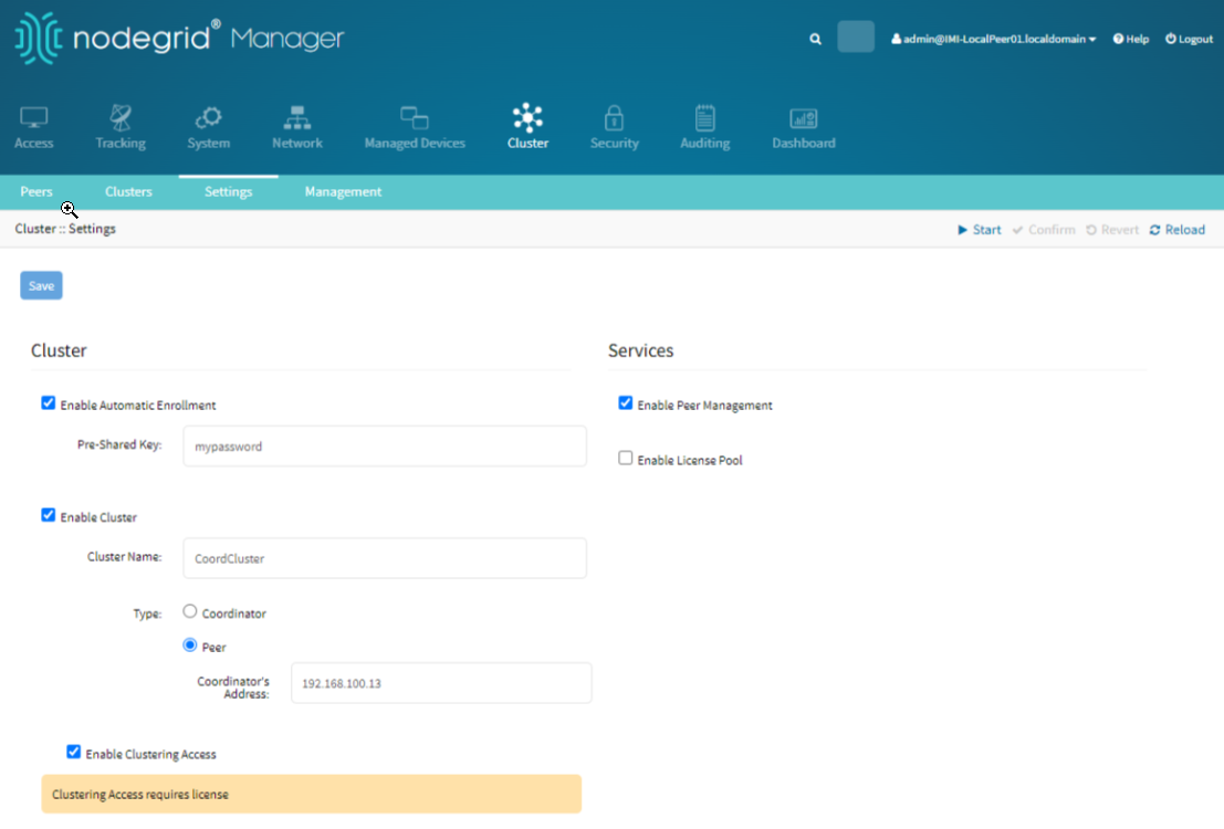
The Peer node needs to be configured to join the existing cluster managed by the Coordinator. This configuration ensures that the Peer can effectively communicate and be managed within the cluster network.
Go to the Cluster tab in the Nodegrid WebUI.
Click the Settings under the Cluster section to access the configuration page.
Check the Enable Cluster box. Enabling the cluster activates the cluster functionality on the Peer, allowing it to join and communicate within the existing cluster network.
Under the Type section, select Peer. This setting designates the device as a Peer, allowing it to join and be managed by the Coordinator.
Set Cluster Name, Coordinator's Address, and PSK:
Enter the cluster name in the Cluster Name field.
Enter the Coordinator's address in the Coordinator's Address field.
Enter the Pre-Shared Key (PSK) in the Pre-Shared Key field.
These settings ensure that the Peer joins the correct cluster and can communicate securely with the Coordinator.
Enable Clustering Access:
Check the Enable Clustering Access option.
This option allows the Peer to access and be managed within the cluster.

Setup System SNMP Settings
Configuring SNMP settings allows for network management and monitoring using SNMP protocols.
Go to Network :: SNMP.
Click Add Community.
Set the community name and access level as required.
Setting up a Super Coordinator
Setup Licenses
The Super Coordinator also requires cluster licenses to function properly.
Go to System > License.
Add Cluster Licenses:
Click the Add License button.
Enter the provided cluster license key.
Click Save to apply the license.
Setup Network Connections
Setting up network failover for the Super Coordinator ensures continuous network availability.
To Enable Network Failover:
Go to Network :: Failover.
Enable network failover.
Set the primary connection to ETH0.
Add LTE as the secondary connection.
Setup Network Settings
Assigning a hostname to the Super Coordinator helps in identifying it within the network.:
Go to Network :: Settings.
Set the hostname to IMI-Super-01.
Setup Super Coordinator Cluster
Setting up the Super Coordinator cluster is similar to the Coordinator but with a different cluster name.
To configure cluster Settings for a super coordinator:
Go to Cluster :: Settings.
Enable the cluster.
Select Coordinator as the type.
Allow enrollment of peers.
Set a Pre-Shared Key (PSK).
Enable clustering access and peer management.
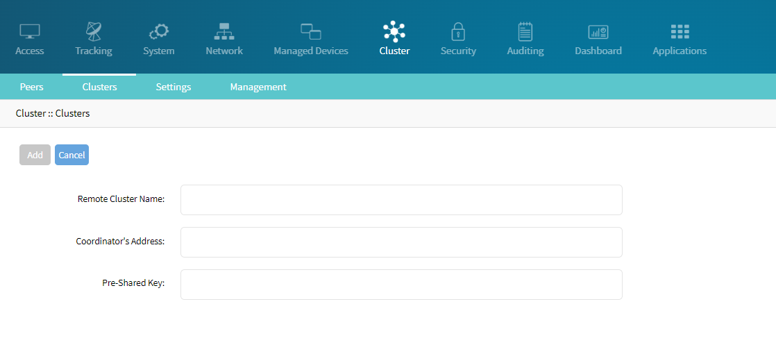
Join in Coordinator's Clusters
The Super Coordinator needs to join existing clusters managed by other Coordinators.
Join Existing Clusters:
Go to Cluster :: Clusters.
Click Join.
Enter the Local Coordinator's information such as Remote Cluster Name, Coordintor’s Address, and Pre-shared Key.

Setup System SNMP Settings
Configuring SNMP settings allows for network management and monitoring using SNMP protocols.
Go to Network :: SNMP.
Click on Add Community.
Set the community’s name and access level as required.
By following these detailed instructions, you can manually configure the Nodegrid Coordinator, Peer, and Super Coordinator to form a robust and efficient cluster network.
Configuring a Wireguard Overlay Network Between Super Coordinator and Coordinator
To establish a secure and efficient Wireguard VPN connection between the Super Coordinator and the Coordinator, follow these detailed steps:
Configure the Super Coordinator Wiregaurd Settings
Go to Network :: VPN :: Wireguard.
Click Add.
Assign an interface name, such as WGVPN.
Set Interface Type to Server.
Set the IP Address to the Super Coordinator's VPN IP (e.g., 10.21.1.1).
Set the Listening Port to 51820.
Click the Generate Keypair button to create a new key pair for the interface.
In the External Address field, enter the Super Coordinator's external IP address (e.g., 172.16.1.1).
Click Save.
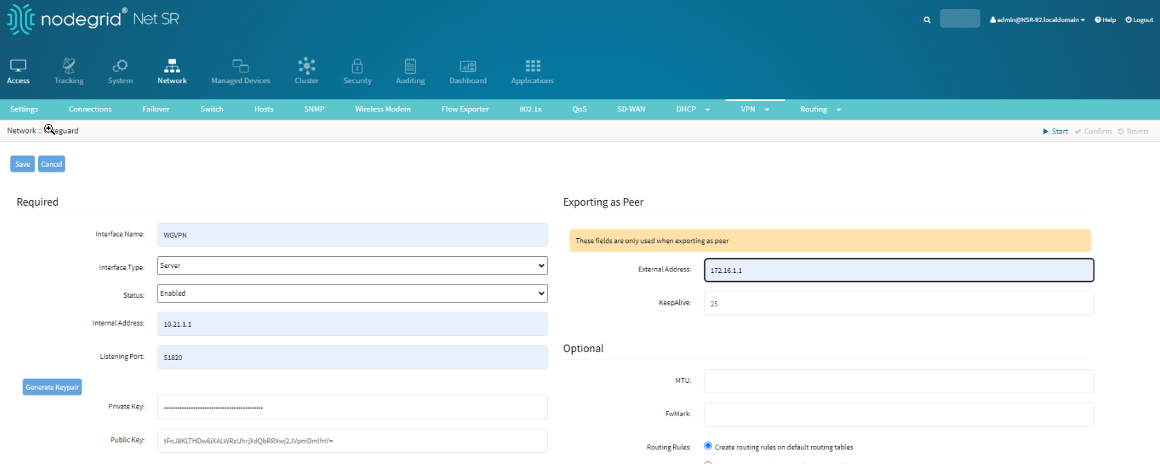
Select the newly added interface.
Click Export as Peer to save the configuration file. This file will be used to configure the Coordinator.
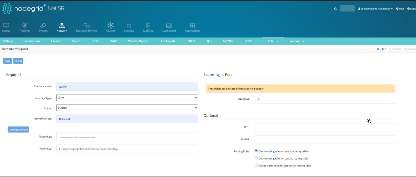
Configure the Coordinator Wiregaurd settings:
Go to Network :: VPN:: Wireguard.
Click on Add to add a new interface.
Assign an interface name, such as WGVPN.
Set Interface Type to Client.
Set the IP Address to the Coordinator's VPN IP (e.g., 10.21.1.11).
Click the Generate Keypair button to create a new key pair for the interface.
Click Save.
Import the Peer Configuration:
Click the newly created interface.
Click Import Peer.
Select the configuration file exported from the Super Coordinator.
Assign a name to the peer.
Click Save.
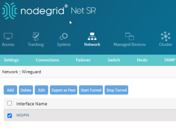
Export the Peer Configuration:
Go back to the interface page.
Select the newly created interface.
Click Export as Peer to save the configuration file. This file will be used to configure the Super Coordinator to recognize the Coordinator as a peer.
Finalize Configuration on the Super Coordinator
Go back to Network :: VPN :: Wireguard on the Super Coordinator.
Select the newly created interface.
Click Import Peer.
Select the configuration file exported from the Coordinator
Assign a name to the peer.
Click Save.


Adding Managed Devices to the Peers
Adding a USB Sensor: Temp/Humidity Sensor
Plugging in a USB sensor for temperature and humidity allows the Nodegrid device to monitor environmental conditions. This process is straightforward and requires minimal configuration.
Plug in the USB Sensor to the peer Nodegrid device. In our case it is an NSCP.
Plug a USB Temp/Humidity Sensor into one of the USB ports of the Nodegrid device.
The sensor will be automatically discovered by the system.
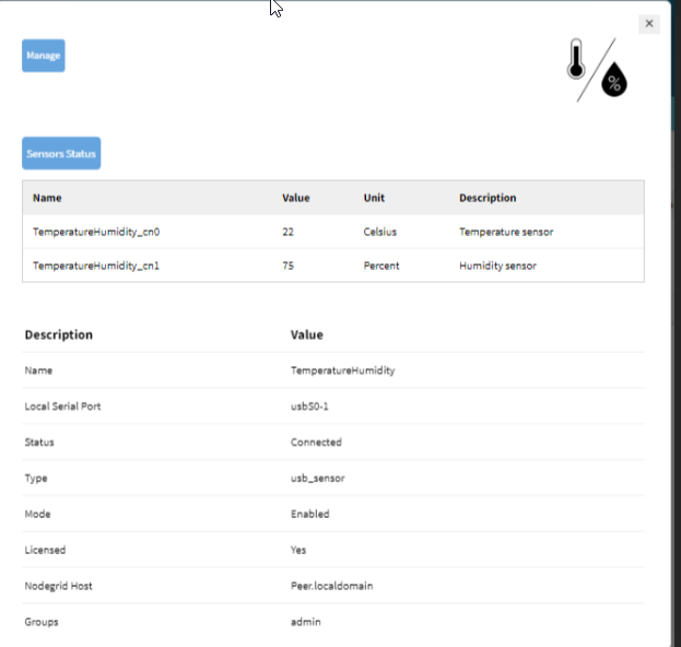
Access the Sensor Data:
Go to Access :: Table in the Nodegrid WebUI.
Click the newly added device.
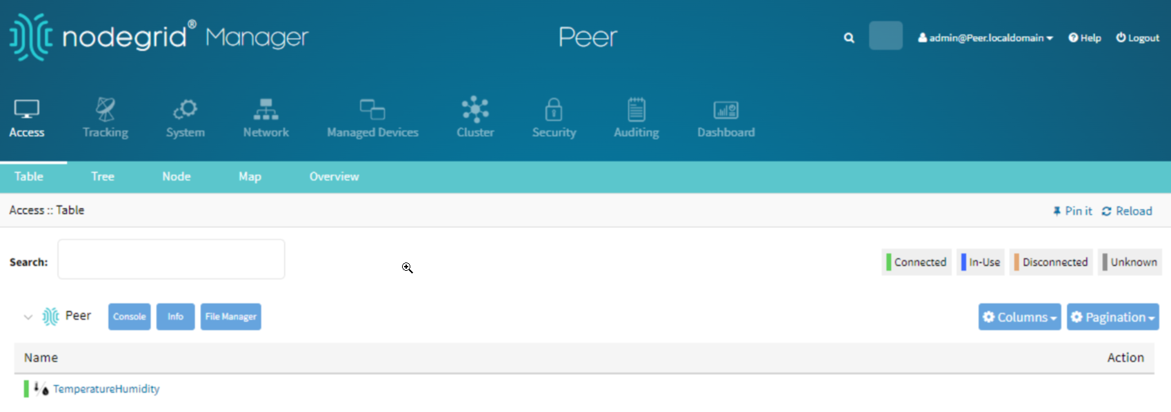
Check the sensor data for temperature and humidity readings.


Addign a ServerTech PDU
Adding and managing a ServerTech PDU allows for remote power management of connected devices.
Add the PDU:
Log in the to peer Nodegrid device.
Go to the Managed Devices.
Click Add.
Give the PDU a name.
Select the type: pdu_servertech.
Fill in the IP address, username, and password.
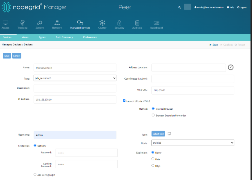
Click Save.

Enable SNMP for PDU: Adding and managing a ServerTech PDU allows for remote power management of connected devices. Configuring SNMP (Simple Network Management Protocol) for the PDU is crucial for enabling network administrators to monitor and manage power distribution units remotely, providing essential data and control over power usage and status.
Click the newly added device.
Go to Management.
Enable SNMP.
Set the community for the PDU.
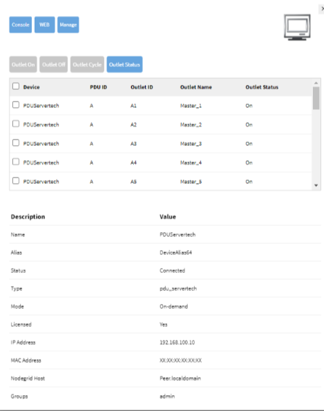
Manage PDU Outlets:
Go to Access :: Table.
Click the PDU device.
Manage its outlets as needed.

Adding Console Devices
Adding console devices allows for remote console access and management.
To add the Console Device:
Go to Managed Devices.
Click Add.
Give the console device a name.
Select the type: device_console.
Fill in the IP address, username, and password.
Click Save.


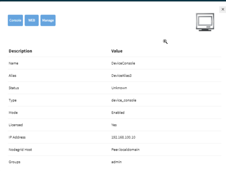
Access the Console:
Perform the following actions, to access the console:
Go to Access :: Table.
Click the console device.
Click Console to access the console interface.

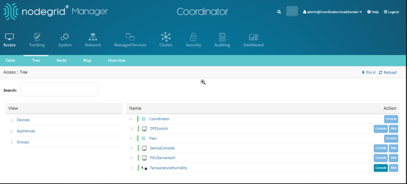
Accessing and Managing Devices Through Tree View
Coordinator Access Tree View
You can access the devices that are managed by the peers through the coordinator. The tree view provides a hierarchical view of all devices and their relationships within the coordinator.
Access the Tree View:
Log in to the local coordinator Nodegrids webUI.
Go to Access :: Tree.

Super Coordinator Tree View
Similar to the coordinator, the super coordinator’s tree view provides an overview of the network hierarchy and device relationships.
To Access the managed devices:
Log in to the webUI of the Super Coordinator.
Go to Access :: Tree.
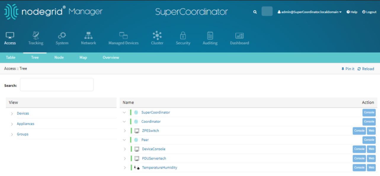

By following these steps, you can effectively manage devices within your Nodegrid setup, ensuring comprehensive monitoring and control over environmental sensors, power distribution units, console devices, and access hierarchies.
Was this article helpful?