Overview
This connection and install guide is intended for an authorized and qualified service person who needs to safely rack mount and install an AC Nodegrid Serial Console Plus (NSCP) in a rack.
After you have completed the installation in this guide, refer to the Nodegrid User Guide for details on how to further configure NSCP.
Verify the NSCP Part Number
Check the part number of the shipment against the device. Part Numbers can be found either on the box containing the unit or underneath the appliance on the product label. The following are the covered part numbers for NSCP.
NSCP-T16R-STND-SAC
NSCP-T32R-STND-SAC
NSCP-T48R-STND-SAC
NSCP-T96R-STND-SAC
NSCP-T16R-STND-DAC
NSCP-T32R-STND-DAC
NSCP-T48R-STND-DAC
NSCP-T96R-STND-DAC
NSCP-T16R-CORE-DAC
NSCP-T32R-CORE-DAC
NSCP-T48R-CORE-DAC
List of Components and Accessories
Component | Included in the Box | Quantity | Comments |
|---|---|---|---|
NSCP AC Appliance | Yes | 1 | |
Rack Mount Ears and Screws | Yes | 2 | |
Console Cable and Adapter | Yes | 1 | |
C13 AC Cables | No | 1-2 | For SAC units, a single cable is required; for DAC, two cables are needed. |
Screwdriver | No | 1 | Philips size #2 |
Cage Nuts | No | 4 | |
Velcro Strips | No | 8+ |
Warnings and Cautions
Read all the following safety guidelines before proceeding with the connections to protect yourself and your Nodegrid Serial Console Plus.
WARNINGS
Do not operate your ZPE Systems Nodegrid Serial Console Plus with the chassis cover removed. This is a Class A product. In a domestic environment, this product may cause radio interference, in which case the user may be required to take appropriate measures.
CAUTION:
To avoid shorting out your ZPE Systems Nodegrid Serial Console Plus when disconnecting the network cable, first, unplug the cable from the Host Server, unplug external power (if applicable) from the equipment, and then unplug the cable from the network jack.
When reconnecting a network cable to the back of the equipment, first plug the cable into the network jack and then into the host server equipment.
To help protect the ZPE Systems Nodegrid Serial Console Plus from electrical power fluctuations, use a surge suppressor, line conditioner or uninterruptible power supply.
Be sure that nothing rests on the cables of the console server and that they are not located where they can be stepped on or tripped over.
Do not spill food or liquids on the console server.
Nodegrid Serial Console Plus may reboot with surge of -2kV at the input power.
Do not push any objects through the openings of the ZPE Systems Nodegrid Serial Console Plus. Doing so can cause fire or electric shock by shorting out interior components.
Keep your ZPE Systems Nodegrid Serial Console Plus away from heat sources and do not block host’s cooling vents.
To reduce the risk of fire, use only No. 26 AWG or larger UL Listed or CSA Certified Telecommunication Line Cord (for example, 24 AWG or 0.25mm2).
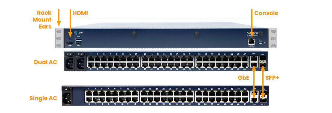
Descriptions and Specifications
Device Overview
Specifications
This section summarizes the physical and environmental specifications of the NSCP device.
Physical
Front-Rear Mounting Brackets
Size (L X W X H): 443 X 312 X 43 mm (17.4 X 12.3 X 1.7 in), 1U
Weight: 5.265 kg (11.6 lb), depending on options
Shipping Weight: 8.745 kg (19.3 lb)
Shipping (L X W X H): 533 X 497 X 209 mm (21 X 19.6 X 8.3 in)
Environmental
Operation: -20 to 55° C (32ºF to 140° F), 5-95% RH, non-cond.
Storage: -20 to 67° C (-4ºF to 153° F), 5-95% RH, non-cond
Power Specifications
Single or Dual AC: 100-240 VAC, 50/60 Hz
Power consumption (Typical): 45 W
Heat Dissipation (Typical): 155 BTU/h
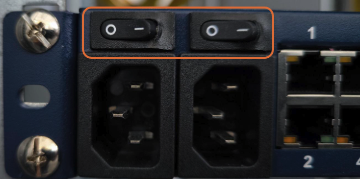
Power Block
The NSCP AC devices have a single or dual power supply, depending on the selected model. Dual AC model provides power redundancy for the appliance.
It is recommended that the power cables be affixed to an appropriate cable management solution, observing the minimum bending radius for the cables.
IMPORTANT
The cable-specific requirements, like bending radius, must be confirmed with the cable vendor.
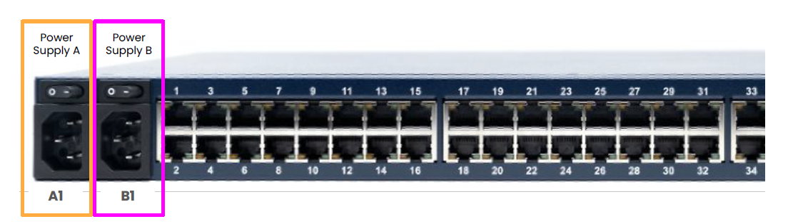
Key | Power Supply | Description |
|---|---|---|
A1 | 1 | Power On and Off switch |
B1 | 1 | Power On and Off switch |
Earth Cable Requirements
The cables connecting the NSCP AC must conform to local electrical, fire, and other security regulations. The requirements provided here are used as a guideline for the customer and do not replace existing rules. A dedicated ground cable must be used. It must be AWS6 or 4mm or larger in diameter.
The Terminal ring size should correspond to M4. The cable should be attached to the unit with the provided screws and a torque of 1.3 to 1.8 N-m.
Grounding
WARNING
This equipment must be grounded. Never operate it without a suitably installed ground conductor. If you are uncertain whether suitable grounding is available, contact the appropriate electrical inspection authority or an electrician.
The NSCP AC devices must be appropriately electrically grounded. The NSCP appliance offers on the left-hand side of the appliance is the ground/earth screw for this purpose.
Device Installation
NSCP devices are designed to be installed into a data center rack. They must be installed into racks with appropriate cable management solutions. Racks offer various cable management options, and users can implement their specific cable management guidelines, such as side cable management options.
Read all the safety guidelines (WARNING and SAFETY Section) before proceeding with the connections to protect yourself and your Nodegrid Serial Console Plus.
The NSCP device cable management can be done using cable management solutions provided by the rack manufacturer and directly integrated into the rack, or device cable management can be performed by adding cable management solutions like lacing bars.
This guide will only outline a validated installation into a rack with a built-in cable management solution. The solution must provide cable management options on the left side of the unit. Additional cable management options can be provided as long as they do not impede the cable management on the left.
IMPORTANT
Appropriate cable management is an integral part of correctly using and installing the provided AC equipment. There is no “one“ proper way of performing cable management; therefore, some judgment must be made. At the core, cable management must fully support the following functions.
avoid any trip hazards, accidental and through negligence
avoid the accidental disconnection of connections or cables
provide a safe work environment
Installation
Users may decide to implement their own guidelines, but the following general requirements must be observed for the installation of NSCP AC:
Observe the minimum bending radius for the used power cable for non-motion.
For example, the cable with an 8 mm diameter should have a typical non-moving minimum bending radius of 48 mm. The cable should be attached to the unit with the provided screws and a torque of 1.3 to 1.8 N-m.
WARNING
Check the cable specification before the installation for cable-specific details.
Affix the AC power cables to an appropriate mounting facility provided by the rack.
AC power cables should be guided to the left side and console cables to the right, separating power and other passive cabling clearly.
Rack Mount and Cable Management
WARNING
Installation must be performed by a certified and trained electrician. Incorrect installation can result in personal injury or equipment damage.
Always power off the unit using the power safety switch on the appliance.
The unit must be correctly grounded using the provided options. Failure to do so may result in the unit being grounded through personnel who touch it, posing a danger to human safety.
Attach ear mounts from the NSCP accessory box using the Phillips #2 screwdriver and provided screws to the unit.
Select an appropriate rack space with enough space to safely install the unit.
Install the cage nuts.
Connect the ground cable to the appliance using the available ground screw on the left-hand side. The cable should be attached to the unit with the provided screws and a torque of 1.3 to 1.8
N-m as shown in the following example diagrams.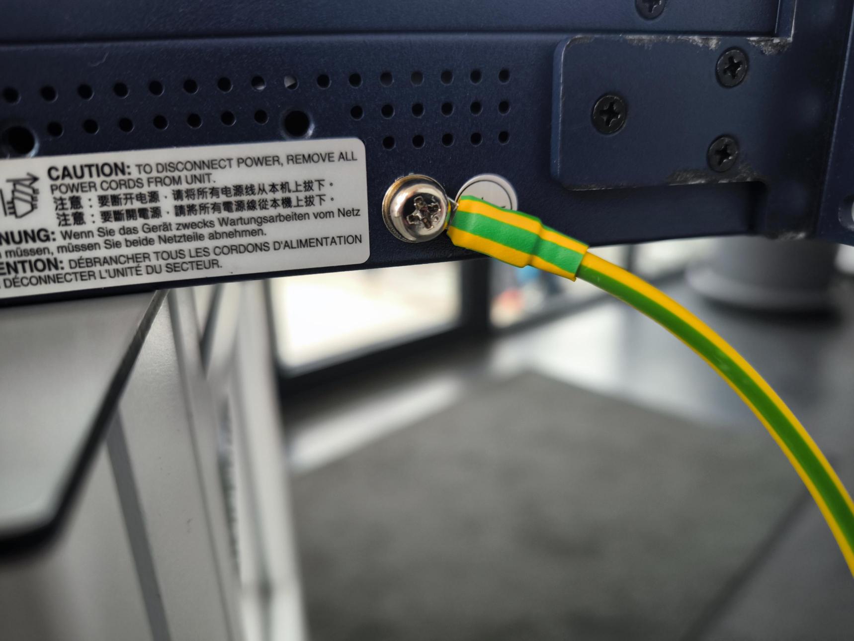
.png)
Connect the Ground Cable to an appropriate ground.
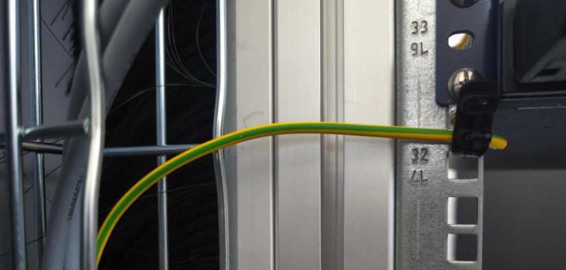
IMPORTANT
Bending Radius: The cables with a minimum bending radius of 48 mm, and the earth cable with a minimum bending radius of 35 mm. The minimum bending radius indicates that the cable can not be bent any further.
WARNING
Ensure that the cables are not connected to any active power source when connecting them to the NSCP AC unit. Always power off the unit using the power safety switch provided by the unit.
The unit must be correctly grounded using the provided options. Failure to do so may result in the unit being grounded through personnel who touch it, posing a danger to human safety.
Do not exceed the maximum bending radius for the cables during installation. Check with the cable manufacturer for the allowed bending radius.
Never touch the power connectors while the AC power source operates. Contact with live connectors may cause electrical shock or damage to the equipment.
Terminate cables with round connectors to prevent accidental disconnections and reduce tripping hazards.
INFORMATION
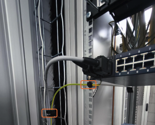
For a safe installation, follow these guidelines when routing cables through rack installation:
Secure cables using flexible, reusable straps or other mechanisms to ensure they are firmly held and cannot be easily moved.
Secure the cables every 40cm or less
Secure the cables as close as possible on each side to the power connection.
Connect NSCP to AC Power Source
IMPORTANT
Always follow local health and safety regulations, especially when working on electrical power lines.
WARNING
The installation of an NSCP AC unit and the connection and any modifications, which include the AC power supply, must be performed by a certified and trained electrician!
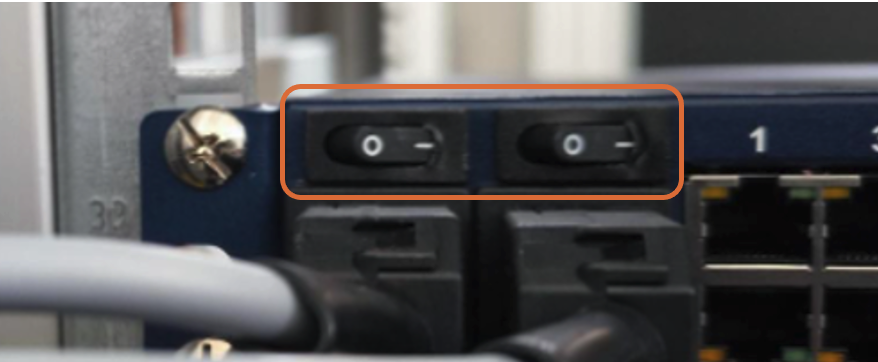
Make sure both power switches on NSCP are turned OFF. The power switch flipped to the left indicates the OFF setting.
WARNING
Ensure the cables are not connected to any active power source when connecting them to the NSCP AC unit. Always power off the unit using the power safety switch provided by the unit.
Make sure the AC main power source is turned off.
WARNING
Never work on powered (hot) wires.
Ensure the power outlet to which the units will be connected is turned off
Power Supply A:
Plug the C13 power cable into the appropriate power socket on the NSCP
Run the power cable to the left, observing a minimum bending radius of 48mm.
Power Supply B:
Plug the C13 power cable into the appropriate power socket on the NSCP
Run the power cable to the left, observing a minimum bending radius of 48mm.
WARNING
Ensure the cable is not bent too tightly and follows the minimum bending radius.
Finish Installation for all units
Using a flexible cable strip, affix both AC cables as close as possible to the cable management system.
The cables must be fixed to the cable management every 40 cm (1.3 feet) or less to avoid accidental movement and provide appropriate cable relief.
Double-check that the AC power source is off, then connect the power cables to the power source, connecting Power Supply A first, then Power Supply B (if applicable).
If required for local configuration, connect any other cables to the appliance, such as device console cables, network cables, and a device console cable.
Turn on both AC power sources.
WARNING
Before continuing, ensure that the unit is properly connected to its power source and that it works as expected to ensure a secure operation of the unit.
The unit must be correctly grounded using the provided options. Failure to do so may result in the unit being grounded through personnel who touch it, posing a danger to human safety.
Turn the unit on using the Power Switches on the unit. The power switch flipped to the right indicates the ON setting.
The unit will power on and boot up.
Connect the console cable to a laptop or other applicable device.
Open a terminal program and connect to the serial console port using the settings 115200, 8, N, 1, N
The console connection will display the boot process until the unit is fully booted and a login prompt is displayed.
The unit is now ready to be configured; see the Nodegrid User Guide for more details at https://docs.zpesystems.com.