Overview
This connection and installation guide is intended for authorized service personnel who need to safely rack mount and install an AC Nodegrid Net Services Router (NSR) in a rack. After completing the installation in this guide, refer to the Nodegrid User Guide for further configuration details.
Verify the NSR Part Number
Check the part number of the shipment against the device. Part Numbers can be found either on the box containing the unit or underneath the appliance on the product label. The following are the part numbers covered by NSR:
ZPE-NSR-48-SAC
ZPE-NSR-48-DAC
ZPE-NSR-48-DDC
ZPE-NSR-48-SAC-POE
ZPE-NSR-48-SDC-POE
ZPE-NSR-88-SAC
ZPE-NSR-88-DAC
ZPE-NSR-88-DDC
ZPE-NSR-88-SAC-POE
ZPE-NSR-88-SDC-POE
ZPE-NSR-48L-DAC
ZPE-NSR-816-SAC
ZPE-NSR-816-DAC
ZPE-NSR-816-DDC
ZPE-NSR-816-SAC-POE
ZPE-NSR-816-SDC-POE
ZPE-NSR-832-SAC
ZPE-NSR-832-DAC
ZPE-NSR-832-DDC
ZPE-NSR-832-SAC-POE
ZPE-NSR-832-SDC-POE
ZPE-NSR-864-DAC
ZPE-NSR-864-DDC
ZPE-NSR-864-SAC-POE
ZPE-NSR-864-SDC-POE
List of Components and Accessories
Component | Included in the Box | Quantity | Comments |
NSR AC Appliance | Yes | 1 | |
Rack Mount Ears and Screws | Yes | 2 | |
Adapter | Yes | 1 | |
C13 AC Cables | No | 1-2 | For SAC units a single cable is required, for DAC 2 cables are required. The cables used should be either C13 to C14 or C13 to the local power socket |
Screwdriver | No | 1 | Philips size #2 |
Cage Nuts | No | 8 | |
Lacing Bars | No | 1 | |
Velcro Strips | No | 2+ |
Warnings and Cautions
Read all the following safety guidelines before proceeding with the connections to protect yourself and your Nodegrid Serial Console Plus.
WARNINGS
Do not operate your ZPE Systems Nodegrid Net Services Router with the chassis cover removed. This is a Class A product. In a domestic environment, this product may cause radio interference, in which case the user may be required to take appropriate measures.
Read all safety guidelines before proceeding with the connections to protect yourself and your Nodegrid NSR.
CAUTION:
To avoid shorting out your Nodegrid NSR when disconnecting the network cable, first unplug the cable from the host server, unplug external power (if applicable) from the equipment, and then unplug the cable from the network jack.
Use a surge suppressor, line conditioner, or uninterruptible power supply to protect the NSR from electrical power fluctuations.
Keep your Nodegrid NSR away from heat sources and do not block the cooling vents.
CAUTION
To reduce the risk of fire, use only No. 26 AWG or larger UL Listed or CSA Certified Telecommunication Line Cord (for example, 24 AWG or 0.25mm2).
Descriptions and Specifications
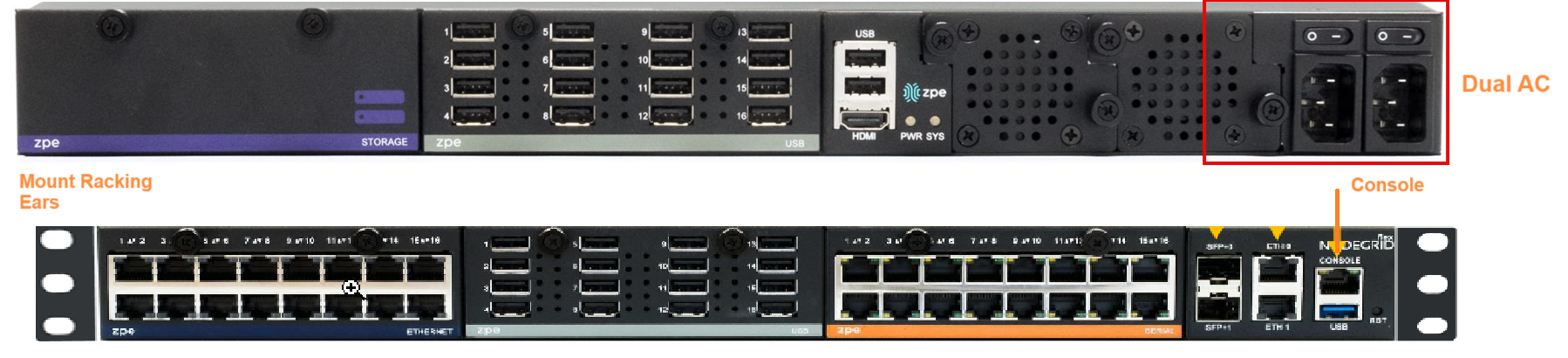
Device Overview
Specifications
This section summarizes the physical and environmental specifications of the NSR device.
Physical
Front-Rear Mounting Brackets
Size (L X W X H): 443 X 312 X 43 mm (17.4 X 12.3 X 1.7 in), 1U
Weight: 5.265 kg (11.6 lb), depending on options
Shipping Weight: 8.745 kg (19.3 lb)
Shipping (L X W X H): 533 X 497 X 209 mm (21 X 19.6 X 8.3 in)
Environmental
Operation: -20 to 55° C (32ºF to 140° F), 5-95% RH, non-cond.
Storage: -20 to 67° C (-4ºF to 153° F), 5-95% RH, non-cond
Power Specifications
40V-63 VDC dual power input (redundant)
Single or Dual AC: 100-240 VAC, 50/60 Hz
Power consumption 45 W typical
Power Block
The NSR AC devices have a single or dual power supply, depending on the selected model. The dual AC model provides power redundancy for the appliance. The power sockets are designed for industry-standard C13 cables. It is recommended that the power cables be affixed to an appropriate cable management solution, observing the minimum bending radius for the cables.
IMPORTANT: The cable-specific requirements, like bending radius, must be confirmed with the cable vendor.
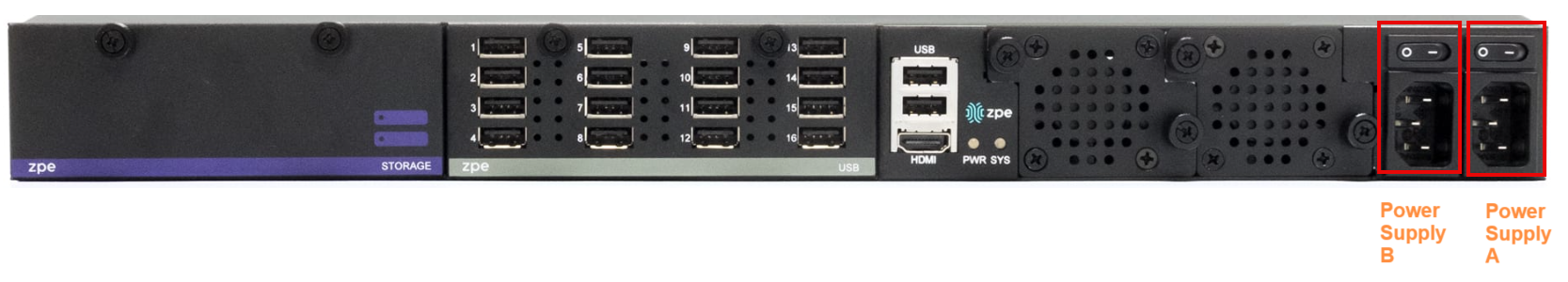
Key | Power Supply | Marking on Unit | Description |
A | 1 | Power On and Off switch | |
B | 1 | Power On and Off switch |
Grounding
The NSR AC devices must be appropriately electrically grounded. The NSR appliance offers two methods for this:
On the left-hand side of the appliance is the ground/earth screw. AC units use this option.
DC units should be grounded using the appropriate ground pins from both terminal blocks.
Installation Guide
NSR devices are designed to be installed into a data center rack. Modern racks offer various cable management options, and customers can implement their specific cable management guidelines. This guideline outlines an installation method using traditional cable management options, which use lacing bars to guide and affix cables. One lacing bar is recommended, either mounted directly above or below the NSR appliance.
Guidelines
Customers may decide to implement their guidelines, but the following general requirements should be observed for the installation of NSR AC:
Observe the minimum bending radius for the used power cables for non-motion. For example, a fire-resistant 4m cable with a 6.6 mm diameter might have a typical non-moving minimum bending radius of 40mm.
IMPORTANT: Check the cable specification before the installation for cable-specific details.
Affix the AC power cables to a lacing bar or other appropriate mounting facility provided by the rack.
AC power cables should be guided to the left side and console cables to the right, separating power and other passive cabling clearly.
Rackmount
Attach ear mounts from the NSR accessory box using the Phillips #2 screwdriver and provided screws to the unit.
Install the cage nuts
Install the NSR unit with the power outlets and console connection facing the installer.
Install the lacing bar below the NSR.
Connect NSR to AC Power Source
IMPORTANT: Always follow local health and safety regulations, especially when working on electrical power lines
Make sure both power switches on NSR are turned OFF. The off position is indicated by the flipped power switch to the left.
Ensure the power outlet to which the units will be connected is turned off.
Starting with Power Supply A:
Plug the C13 power cable into the appropriate power socket on the NSR.
Run the power cable to the lacing bar, then to the left side of the rack.
WARNING: Ensure the cable is not bent too tightly and follows the minimum bending radius.
Affix the cable to the lacing bar with Velcro to prevent it from being moved by mistake or accident.
Repeat steps 3-6 for Power Supply B for DAC units.
Connect the power cables to the power source, starting with Power Supply A, followed by Power Supply B.
Connect any other cables to the appliance, such as device console cables, network cables, and a device console cable.
Turn on both power sources.
The unit will power on and boot up.
Connect the console cable to a laptop or other appropriate device.
Open a terminal program and connect to the serial console port using 115200,8,N,1,N.
The console connection will display the boot process until the unit is fully booted and a login prompt is displayed.
The unit is now ready to be configured; see the User Manual for more details at https://docs.zpesystems.com.
Note
On the Nodegrid Net Services Router with PoE support, the second power supply specifically powers the PoE feature and does not provide power outage redundancy.
When all power supplies are appropriately connected to a power source, power can be turned on.