DC Power
DC power is connected to DC-powered equipment with three wires: Return (RTN), Ground, and 48 VDC.
WARNING
It is critical that the power source supports the DC power requirements of your Nodegrid. Make sure that the power source is the correct type and that the DC power cables are in good condition before proceeding. Failure to do so could result in personal injury or damage to the equipment.
WARNING
Wiring to power from a DC supply may be confusing, especially in telecom racks, where the supply's positive wire (usually of red color) goes to the ground, and the hot wire (usually of black color) carries the -48VDC. In case of any doubt, consult a certified electric technician before proceeding with connections. Failure to do the right connections could result in personal injury or damage to the equipment.
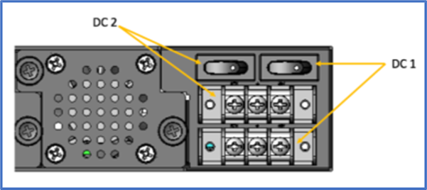
Dual DC Power Connection Terminal Block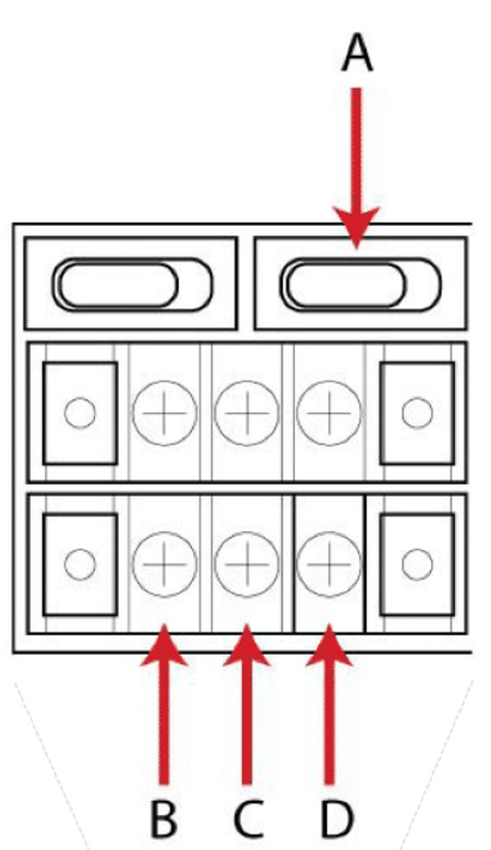
DC Power Block Terminals
Number | Description |
A | Power Switch |
B | RTN (Return) |
C | Ground |
D | 48 VDC |
DC association - terminal power source and switch
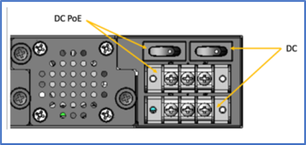
NSR Single DC + PoE Power Connection Terminal Block
Connect a Nodegrid device to DC Power
- Make sure the device is turned off.
- Make sure DC power cables are not connected to a power source.
Never work on powered wires. - On the DC power block, remove the protective cover. (Slide to the left or right to remove.)
- Loosen all three DC power connection terminal screws.
Connect the return lead to the RTN terminal.
Connect the ground lead to the GND terminal. Connect 48 VDC lead to the 48 VDC terminal.
 - Tighten the screws.
- Slide the DC terminal block protective cover back into place.
- If the device has dual-input DC terminals, repeat the DC power connection steps for the second terminal block.
- Connect the DC power cables to the DC power source.
- Turn on the DC power source.
- (optional) Connect a serial client (set as 115200 8N1) to the console port (Teraterm, puTTY, etc).
- Turn the power on to the serial client.
- On the connected serial client, double-check booting messages.
- For the connected devices, turn on the power switches.
- Connect the DC power cables to the DC power source.
- Turn on the DC power source.
- Turn on the unit.
- Turn on the power switches of the connected devices.
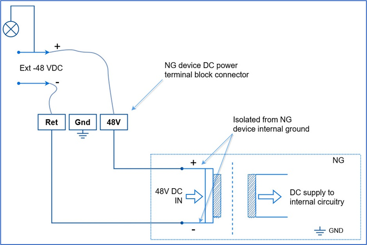
-48VDC supply
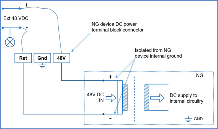
+48VDC supply
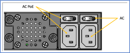
AC Power
This is the AC diagram for the NSR models with PoE+ support.