To perform these procedures, log into the Nodegrid Device.
Access sub-tab
- Go to Managed Devices :: Devices :: Gpio :: Access.
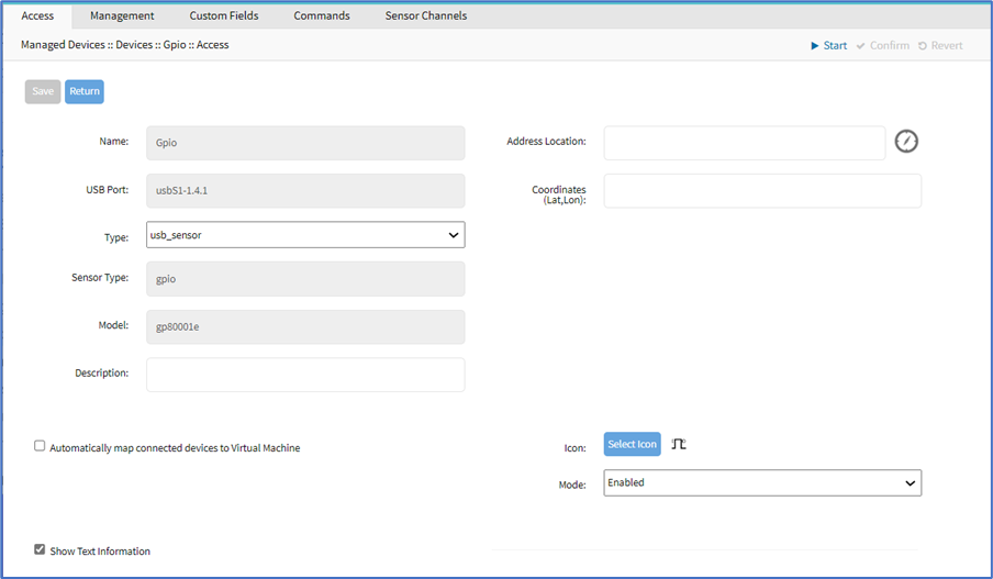
- As needed (many of these are optional):
- On Type drop-down, accept default: usb_sensor.
- Enter Description.
- Enter Address Location.
- Enter Coordinates (Lat,Lon).
- Select Automatically map connected devices to Virtual Machines checkbox. On expanded dialog, enter Virtual Machine Name.

- Click Icon (on pop-up, select the preferred icon).
- On Mode drop-down, select one (Enabled, On-demand, Disabled, Discovered).
- Select Show Text Information checkbox.
- Click Save.
Management sub-tab
- Go to Managed Devices :: Devices :: Gpio :: Management.
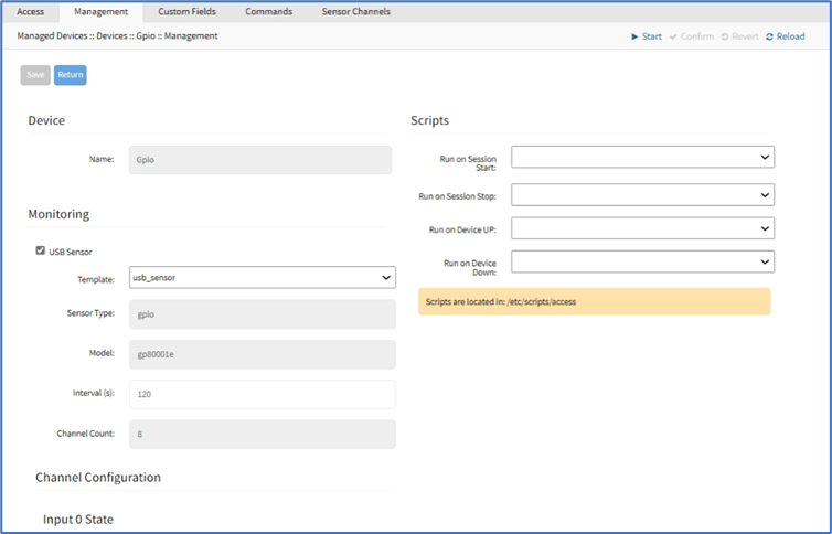
- In the Monitoring menu:
- Select USB Sensor checkbox (expands dialog).
- On Template drop-down, accept default: usb_sensor).
- Enter Interval (s) (default: 120).
- In the Scripts menu: (if scripts are available)
- On Run on Session Start drop-down, select a script.
- On Run on Session Stop drop-down, select a script.
- On Run on Device UP drop-down, select a script.
- On Run on Device Down drop-down, select a script.
- In Channel Configuration menu: Make changes only on Input 2 State.
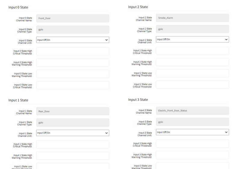
- In Input 2 State menu:
- In Input 2 State Channel Unit drop-down, select default: Input Off/On or Output Off/On
- In Input 2 State High Critical Threshold, enter value.
- In Input 2 State High Warning Threshold, enter value.
- In Input 2 State Low Warning Threshold, enter value.
- In Input 2 State Low Critical Threshold, enter value.
- Click Save.
Custom Fields sub-tab
- Go to Managed Devices :: Devices :: Gpio :: Custom Fields.
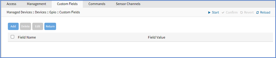
- To create a custom field, click Add (displays dialog).
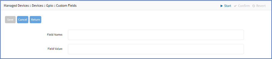
- Enter Field Name.
- Enter Field Value.
3. Click Save.
Commands sub-tab
- Go to Managed Devices :: Devices :: Gpio :: Commands.
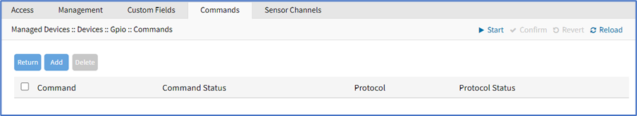
- To create a custom command, click Add.
- In Command drop-down select one (Web, Custom Commands).
- Select Web (displays dialog).
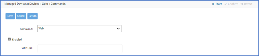 Select Enabled checkbox.
Enter WEB URL. - Select Custom Commands (displays dialog).
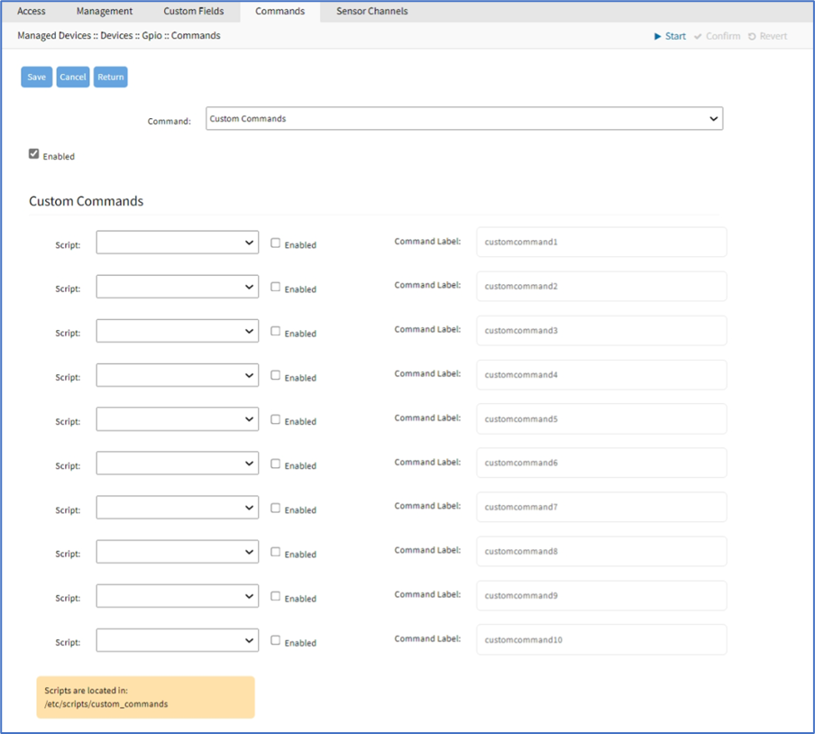 Select Enabled checkbox.
In Script drop-down, select one. Select Enabled checkbox. Enter Command Label.
- Select Web (displays dialog).
- (Repeat as needed)
3. Click Save.
Sensor Channels sub-tab
The table displays configured sensor channels.
- Go to Managed Devices :: Devices :: Gpio :: Sensor Channels.
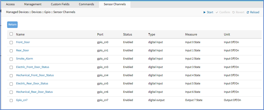
- Click on Smoke_Alarm channel (displays dialog).
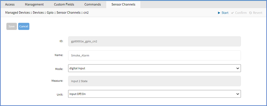
- Edit Name (as needed).
- On Mode drop-down, accept default: digital input.
- On Unit drop-down, accept default: Input Off/On.
- Click Save.