A Passive Optical Network (PON) is a fiber-optic communication system that transmits data over a single optical fiber to multiple endpoints using non-powered splitters. By eliminating the need for active components, PON reduces infrastructure and maintenance costs, making it a cost-effective solution for broadband internet and telecommunication services.
The Nodegrid Gate SR, Hive SR, and Nodegrid Serial Console (model NSC-T48 with SFP) devices support high-speed network connectivity for data center devices by utilizing its SFP+ ports as optical network units (ONUs) transceivers. These ports enable connections to compatible third-party Optical Line Terminal (OLT) that support both GPON (Gigabit Passive Optical Network) .png) and XGS-PON (10 Gigabit Symmetrical Passive Optical Network)
and XGS-PON (10 Gigabit Symmetrical Passive Optical Network) .png) standards. GPON delivers downstream speeds up to 2.5 Gbps and upstream speeds up to 1.25 Gbps, while XGS-PON provides symmetrical 10 Gbps speeds, making the device suitable for high-bandwidth applications in data centers.
standards. GPON delivers downstream speeds up to 2.5 Gbps and upstream speeds up to 1.25 Gbps, while XGS-PON provides symmetrical 10 Gbps speeds, making the device suitable for high-bandwidth applications in data centers.
Benefits
The benefits of using XGS-PON with ZPE Systems’ Nodegrid SR gateway include:
High-Speed Connectivity: XGS-PON delivers symmetrical speeds of up to 10 Gbps, making it ideal for high-bandwidth applications. This ensures consistent and high-quality service for end-users.
Cost-Effectiveness: Deploying XGS-PON is a cost-effective solution for delivering high-speed broadband services, especially in scenarios where upgrading existing infrastructure may be challenging.
Scalability: The Nodegrid SR Gateway, acting as an ONU, can connect up to 256 serial consoles through a single fiber strand. PON’s use of asymmetric wavelengths and TDM enables multiple devices to share the same fiber strand efficiently. Optical splitters, which require no external power, facilitate the sharing of fiber between multiple ONUs, which makes scaling much more cost and energy efficient.
Reliability: The Nodegrid SR gateway’s robust design and compatibility with various network configurations delivers high-quality broadband services.
Nodegrid PON Architecture
This section describes the different components of the Nodegrid GPON and XGS-PON architectures. The following Figures 1 and 2 show architecture of GPON and XGS-PON with Nodegrid respectively.
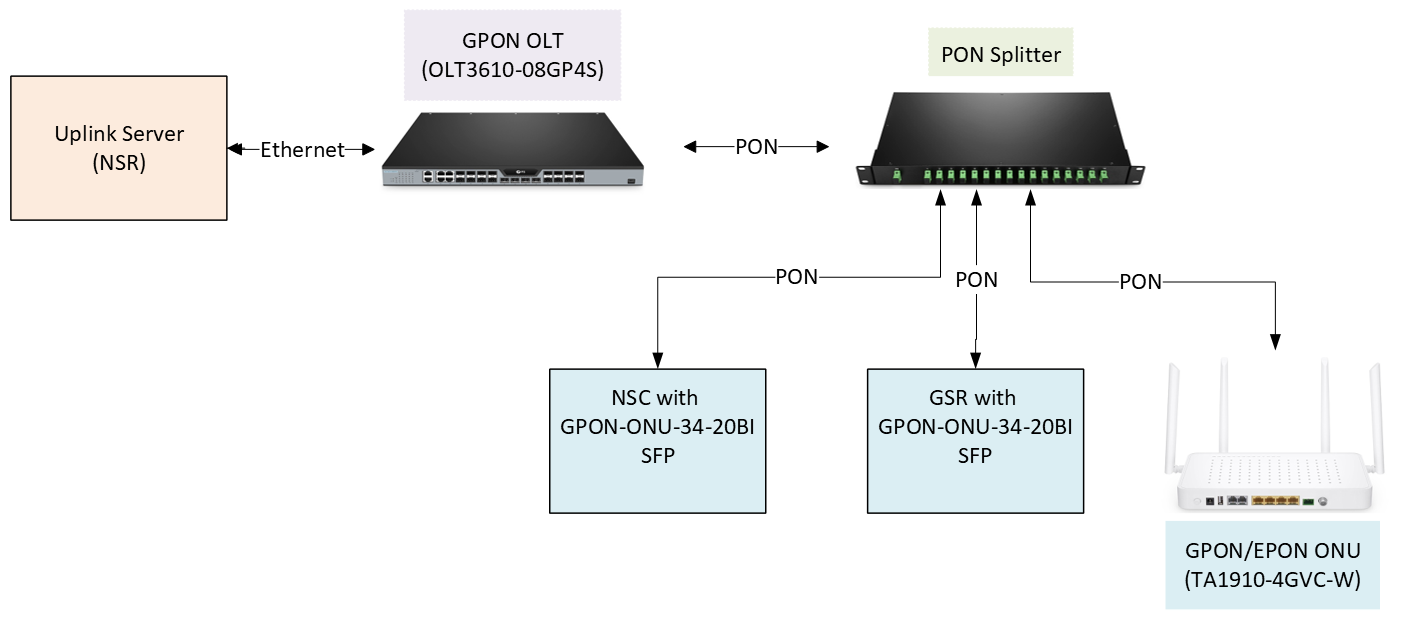
Figure 1: GPON Architecture
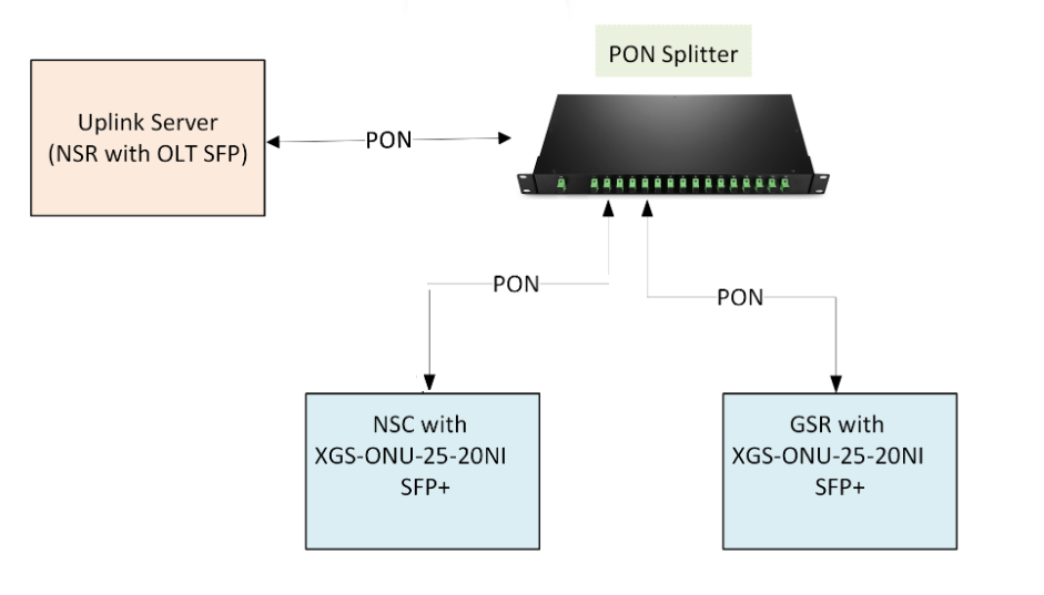
Figure 2: XGS-PON Architecture
Uplink Server
Nodegrid Serial Router (NSR) acts as uplink server. The optical line terminal (OLT) uplink ports connects to a switch, gateway, PPPoE Server, and DHCP Server.
GPON OLT
The OLT3610-08GP4S OLT has four 1G Ethernet ports, four 1G SFP ports and four 10G SFP+ for the uplink connections, and eight GPON ports for the downlink connections. The GPON port with the GSFP-43-20C OLT SFP is connected to the PON splitter through a single fiber.
Fiber Splitter
The fiber splitter PLC-116-1U-SCA splits PON connection from the OLT to up to 16 downlink ONU/ONT devices. A single fiber strand can be shared among hundreds of out-of-band and serial console devices using passive optical splitters.
Optical Network Unit or Optical Network Terminal
Gate SR and NSC with ONU device SFP
The Gate SR and NSC required an ONU Stick SFP with MAC to connect to the fiber splitter. The GPON-ONU-34-20BI ONU Stick SFP with MAC was used in Gate SR and NSC to terminate the PON connection. This SFP model includes the Media Access Control (MAC) functionality, so it does the conversion of the PON signals to MAC. It appears to the OS just as a regular Ethernet interface. The GPON-ONU-34-20BI ONU Stick SFP is running BusyBox and accepts SSH connection.
The ONU device SFP without MAC would not work in Gate SR and NSC as the SFP section in Gate SR and NSC does not contain hardware to terminate the PON connection.
ONU device
The TA1910-4GVC-W optical network unit (ONU) device is connected to the fiber splitter. The ONU device has a DHCP Server that can provide IPs to its clients, or it can send the DHCP requests from its clients to the uplink server in bridge mode. The ONU device can also be configured with PPPoE, in which case a PPPoE Server is required in the OLT uplink.
Ethernet or VLAN Connection with 802.1x Authentication
When connecting the Nodegrid device SFP+ ports to an uplink server that requires 802.1X authentication, ensure the 802.1X authentication is enabled in Nodegrid to establish a secure, authenticated connection for authorized network access. Follow these steps to enable 802.1x supplicant on an Ethernet or VLAN connection.
From the Web
Go to Network :: Connections.
Click the Ethernet or VLAN connection.
Check the Enable the 802.1x Supplicant checkbox.
Select the Authentication Method.
For tls:
Enter the Username for network access.
Enter the path to the Client Certificate to authenticate the identity of the device.
Enter the path to the Client Private Key, which is used to establish secure connection.
Enter the Client Private Key Password.
Enter the path to the CA Certificate to validate the server certificate to validate server’s authenticity.
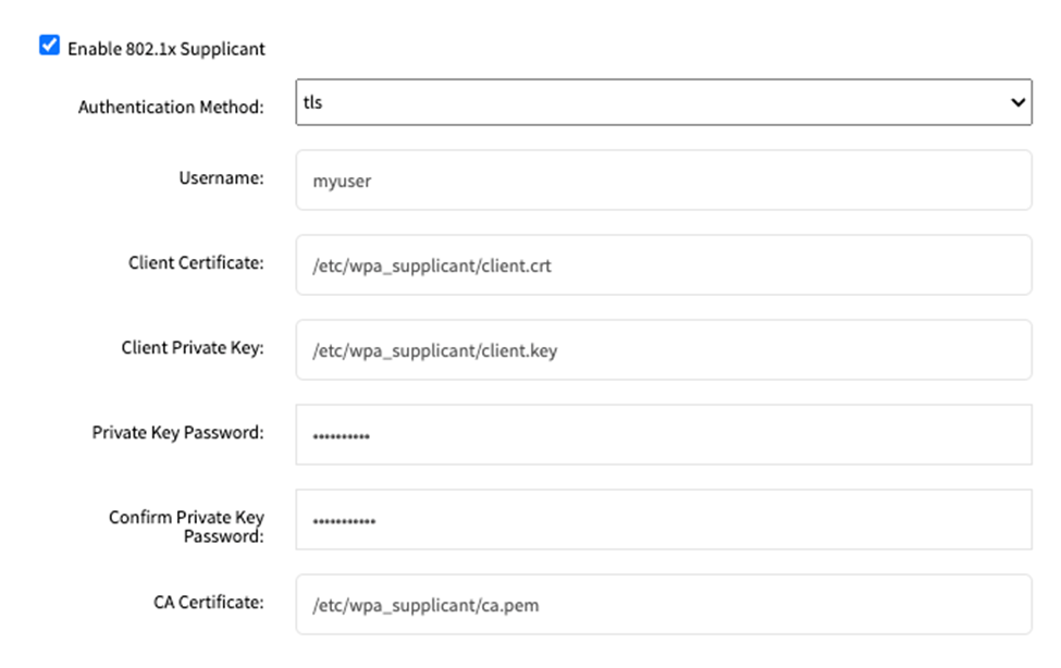
For ttls:
Enter the Username for network access.
Enter the Password associated with the above mentioned username to complete the authentication process.
Enter the Anonymous Identity for the user.
Enter the path to the CA Certificate to validate the server certificate.
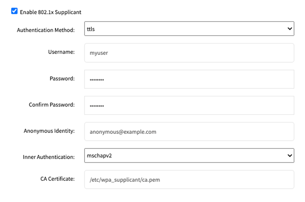
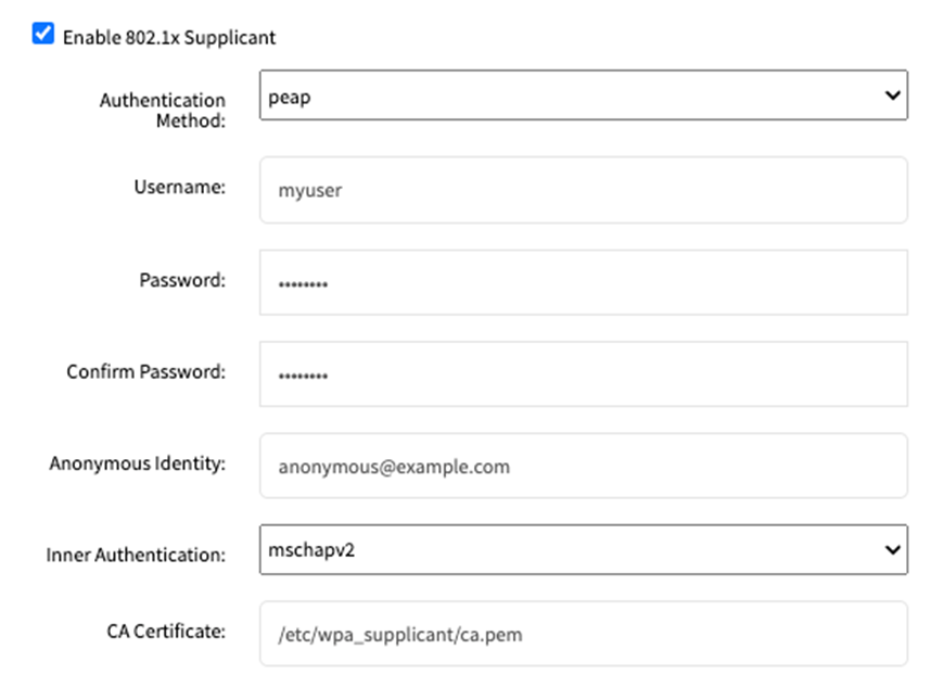
For peap:
Enter the Username for network access.
Enter the Password associated with the above mentioned username to complete the authentication process.
Enter the Anonymous Identity for the user.
Enter the path to the CA Certificate to validate the server certificate.
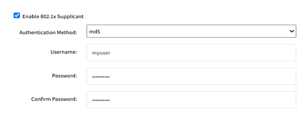
For md5:
Enter the Username for network access.
Enter the Password associated with the above mentioned username to complete the authentication process.
From CLI
Go to an Ethernet or VLAN connection and enable the 802.1x supplicant.
cd system/network_connections/<connection>
set enable_802.1x_supplicant=yes
Example:
[admin@pon-gsr /]# cd settings/network_connections/SFP1
[admin@pon-gsr SFP1]# set enable_802.1x_supplicant=yes
The default authentication method is tls. To view the configuration, enter:
showExample:
[+admin@pon-gsr SFP1]# show
name: SFP1
type: Ethernet
ethernet_interface = sfpl
description =
connect_automatically = no
set_as_primary_connection = no
enable _lldp = no
enable _802.1x_supplicant = yes
802.lx _authentication_method = tls
** Requ i red: 802 . lx_username , 802.lx_client_certifi cate, 802.lx_cli ent _private_k
ey , 802.lx_private_key _password **
802.lx _username =
802.lx _client_certificate =
802.lx _client_private_key =
802.lx _private_key_password =
802.lx ca certifi cate=
To configure the 802.1x for tls, enter:
set 802.1x_username=<client Identity>
    802.1x_client_certificate=<path to the client certificate file>
    802.1x_client_private_key=<path to the client private key file>
    802.1x_private_key_password=<client private key password>
set 802.1x_ca_certificate=<path to the CA certificate>
Example:
[+admin@pon- gsr SFP1]# set 802.lx_username=myuser 802.lx_cl ient_certificate=/etc
/wpa _supplicant/client.crt 802.lx_client _private_key=/etc/wpa _supplicant/client.
key 802.lx_private_key_password=mypassword
[+admin@pon-gsr SFPl]# set 802.lx_ca _certificate=/etc/wpa_supplicant/ca.pem
Set 802.1x_username, 802.1x_client_certificate, 802.1x_client_private_key and 802.1x_private_key_password in the same line.
Set 802.1x_ca_certificate to validate the server certificate; if this setting is empty, the server validation is skipped, which is not recommended.
To configure authentication method peap, enter:
set 802.1x_authentication_method=peap
set 802.1x_username=<client Identity>
    802.1x_password=<client password>
    802.1x_anonymous_identity=<unencrypted identity>
set 802.1x_inner_authentication=<select phase 2 authentication>
set 802.1x_ca_certificate=<path to the CA certificate>
Example:
[+admin@pon-gsr SFPl]# set 802.lx_authentication_method=peap
[+admin@pon-gsr SFPl]# set 802.lx_username=myuser 802.lx_password=mypassword 802
.1x_anonymous_identity=anonymous@example.com
[+admin@pon-gsr SFPl]# set 802.1x_inner_authentication=mschapv2
[+admin@pon-gsr SFPl]# set 802.lx_ca _certificate=/etc/wpa_supplicant/ca.pem
Set 802.1x_username, 802.1x_password and 802.1x_anonymous_identity in the same line.
Set 802.1x_ca_certificate to validate the server certificate; if this setting is empty, the server validation is skipped, which is not recommended.
To configure authentication method ttls, enter:
set 802.1x_authentication_method=ttls
set 802.1x_username=<client Identity>
    802.1x_password=<client password>
    802.1x_anonymous_identity=<unencrypted identity>
set 802.1x_inner_ausethentication=<select phase 2 authentication>
set 802.1x_ca_certificate=<path to the CA certificate>
Example:
[+admin@pon-gsr SFPl]# set 802.lx_authentication_method=ttls
[+admin@pon-gsr SFPl]# set 802.lx_username=myuser 802.lx_password=mypassword 802:
.1x_anonymous_identity=anonymous@example.com
[+admin@pon-gsr SFPlJ# set 802.1x_inner_authentication=mschapv2
[+admin@pon-gsr SFPl]# set 802.lx_ca_certificate=/etc/wpa_supplicant/ca.pem
Set 802.1x_username, 802.1x_password and 802.1x_anonymous_identity in the same line.
Set 802.1x_ca_certificate to validate the server certificate; if this setting is empty, the server validation is skipped, which is not recommended.
To configure authentication method md5, enter:
set 802.1x_authentication_method=md5
set 802.1x_username=<client Identity> 802.1x_password=<client password>
Example:
[+admin@pon-gsr SFP1]# set 802.1x_authentication_method=md5
[+admin@pon-gsr SFP1]# set 802.lx_username=myuser 802.lx_password=mypassword
To commit the changes, enter:
commitIf you want to revert the changes, enter:
revert
Viewing PON Diagnostics
This section describes the steps to view the PON diagnostics using the Nodegrid application. The PON diagnostics page in Nodegrid enables users to view the PON information without the need to perform an SSH or telnet to access the Webpage of the ONU device. You can run PON Diagnostics to view the ONU information, PON Serial Number, PON State, or get the transceiver readings.
From the Web
Log in to the Nodegrid UI.
Navigate to Tracking :: Network and select the interface that has PON SFP. In this configuration, the Gate SR device’s SFP0 and SFP1 ports are used.
.png) The interface Statistics are displayed.
The interface Statistics are displayed.NOTE:
If the SFP transceiver is a supported GPON or XGS-PON ONU stick, the PON Diagnostics button will be shown.Click sfp0. A page opens providing the sfp0 details and the PON Diagnostics button. You can notice that sfp0 is compatible with GPON as indicated in the following figure:
.png)
Click PON Diagnostics. The PON Diagnostics page is displayed.
.png)
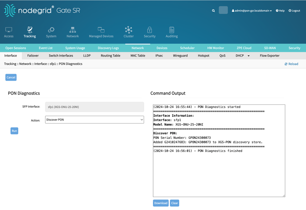
The first time the PON Diagnostics page opens with a new XGS-ONU-25-20NI transceiver, the action Discover PON is displayed. The Under Action, select the option Discover PON and click Run before running other options. Discover PON takes around 20 seconds to complete.
For the other actions, the diagnostics output will depend on the transceiver model. Select the required Action and click Run:
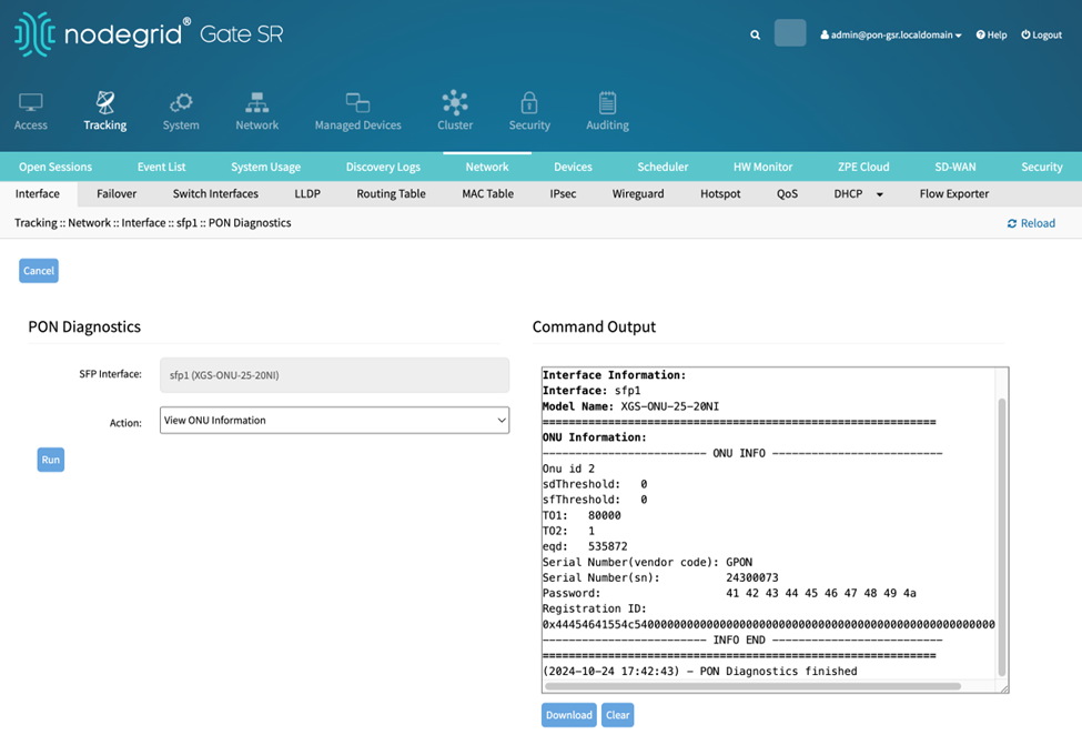
Running action View ONU Information with the XGS-ONU-25NI displays the ONU information.
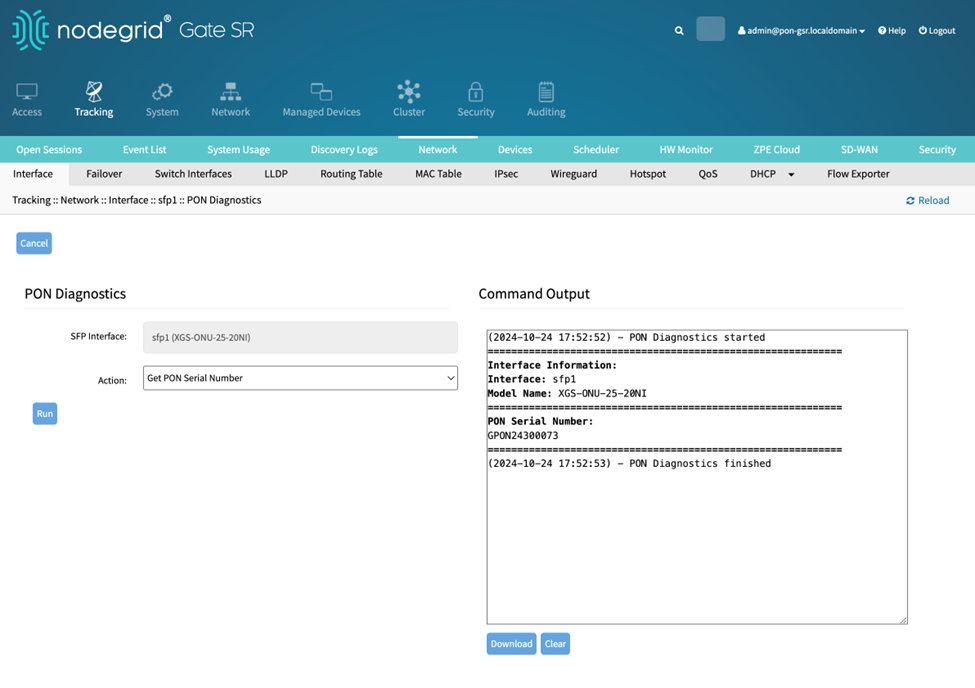
Running action Get PON Serial Number displays the PON Serial Number.
Running action Get PON State displays the PON activation state.
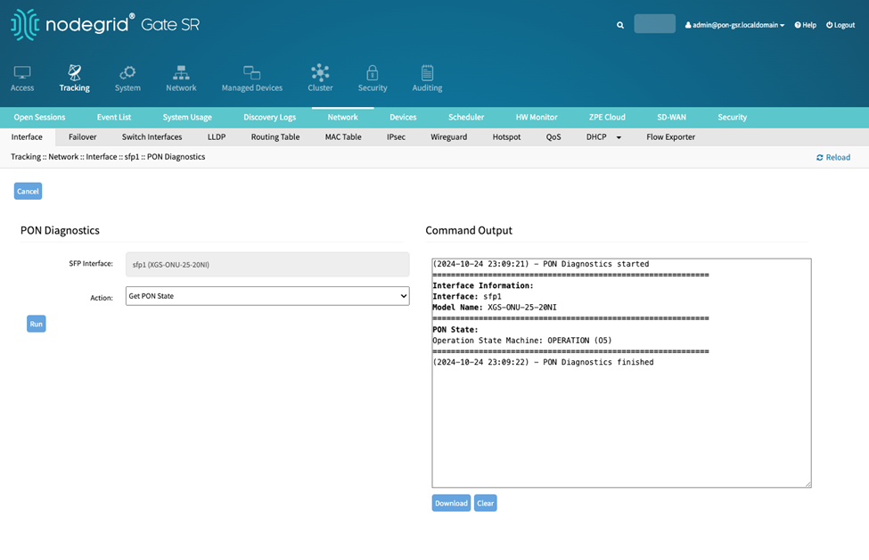
There are 5 states in the ONU activation process:
Initial state (01)
Standby state (02)
Serial Number state (03)
Ranging state (04)
Operation state (05)
There are two additional states in a GPON ONU and XGS-PON:
The GPON ONU can transition to but are not part of the activation:
POPUP state (06)
Emergency Stop State (07)
The XGS-PON ONU additional states are:
IntermittentLODS state (06)
Emergency Stop State (07)
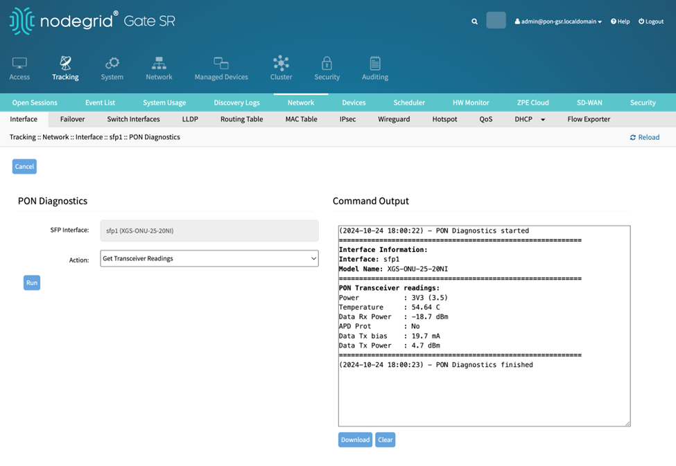
Running action Get Transceiver Readings with XGS-ONU-25-20I returns the Power Voltage, Temperature, Data Rx Power, APD Port, Data Tx bias and Data Tx Power.
From CLI
To view the network interface statistics, including the SFP information:
# cd system/network_statistics/<interface>
# show
If the SFP is a supported PON SFP, the “pon_diagnostics” command will be listed when pressing the Tab key twice. Run:
# pon_diagnosticsThe first time the “pon_diagnostics” is called with a new XGS-ONU-25-20I transceiver, the action “discover_pon” is displayed. The action “discover_pon” needs to be executed once before other actions:
# show
sfp interface: sfp1 (XGS-ONU-25-20NI)
action = discover_pon
# run_diagnostics
Select the desired action and run the corresponding diagnostics:
# set action=<desired action>
# run_diagnostics
NOTE:
Press Tab twice after “set action =” to view the available actions.
Running action “view_onu_information” with the XGS-ONU-25NI returns the ONU information:
# set action= view_onu_information
# run_diagnostics
Running action “get_pon_serial_number” returns the PON Serial Number:
# set action= get_pon_serial_number
# run_diagnostics
Running action “get_pon_state” returns the PON activation state:
# set action= get_pon_state
# run_diagnostics
There are 5 states in the ONU activation process:
Initial state (01)
Standby state (02)
Serial Number state (03)
Ranging state (04)
Operation state (05)
There are two additional states in a GPON ONU and XGS-PON:
The GPON ONU can transition to but are not part of the activation:
POPUP state (06)
Emergency Stop State (07)
The XGS-PON ONU additional states are:
IntermittentLODS state (06)
Emergency Stop State (07)
Running action “get_transceiver_readings” with XGS-ONU-25-20I returns the Power Voltage, Temperature, Data Rx Power, APD Prot, Data Tx bias and Data Tx Power:
# set action= get_transceiver_readings
# run_diagnostics