With bonding interfaces, the system can bond two or more physical network interfaces to one interface. All physical interfaces in the bond act as one interface. This allows for an active failover between the interfaces if an interface's physical connection is interrupted.
The built-in Network Failover can do the same. The main difference is that the built-in feature Network Failover works on the IP layer for more functionality. A bonding interface works on the link layer.
NOTE
- The Network Failover and Bonding functions can be combined.
- When using a Bonding interface, ensure that the DNS configuration is valid (reachable DNS). This allows the Nodegrid device to reconnect to the ZPE Cloud.
The administrator can define normal network settings (IP address, bitmask, and other settings) for the bonding interface.
- Go to Network :: Connections.
- Click Add (displays dialog).
- Enter Name.
- On Type drop-down, select Bonding (dialog changes).
.png)
- Enter Description.
- Select checkboxes as needed:
- If Connect Automatically checkbox is selected, connection is automatically established at startup.
- Set as Primary Connection checkbox (defines interface as the primary connection. Only one interface can be the primary.)
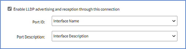
- Enable LLDP advertising and reception through this connection checkbox. On Port ID drop-down, select one. On Port Description drop-down, select one.
- Block Unsolicited Incoming Packets checkbox (automatically blocks all inbound connections on the interface).
- In Bonding Connection menu, in the optional Interface field, enter the name of the bonding interface that will be created for this connection. If not entered, the interface will be called bondN, where N is a number starting at 0 and automatically incremented as needed.
- In Bonding Connection menu, Bonding Mode drop-down, select one (dialog changes):
- Round-robin (packets transmitted in sequential order from first available slave through the last)
- Active backup (only one slave in the bond is active. A different slave becomes active if, and only if, the active slave fails)
- XOR load balancing (transmit based on the selected transmit hash policy)
- Broadcast (transmits everything on all slave interfaces)
- 802.3ad(LACP) (IEEE 802.3ad Dynamic link aggregation. Creates aggregation groups that share the same speed and duplex settings. Utilizes all slaves in the active aggregator according to the 802.3ad specification. Slave selection for outgoing traffic is done according to the transmit hash policy)
- Adaptive Transmit load balancing (channel bonding that does not require any special switch support. Outgoing traffic is distributed according to the current load (computed relative to the speed) on each slave. Incoming traffic is received by the current slave)
- Adaptive load balancing (includes balance-TLB plus receive load balancing - RLB for IPV4 traffic. Does not require any special switch support. Receive load balancing is achieved by ARP negotiation)
- Enter the list of interfaces that participate on the bond:
- Primary Interface and Secondary Interface drop-down menus (when Active backup mode is selected)
- Slave(s) interface(s) (comma separated) (when any other mode is selected)
- Primary Interface and Secondary Interface drop-down menus (when Active backup mode is selected)
- Configure the Link Monitoring method according to the chosen bonding mode:
- Link Monitoring drop-down, select one (MII, ARP):
- MII (monitors the carrier state as sensed by the interface). The following configuration options apply to this mode:
- Monitoring Frequency (ms) (how often the link state of each slave is inspected for link failure)
- Link Up delay (ms) (time to wait before enabling a slave after a link recovery has been detected. Should be a multiple of Monitoring Frequency)
- Link Down delay (ms) (time to wait before disabling a slave after a link failure has been detected. Should be a multiple of Monitoring Frequency)
- ARP (monitors connectivity to another host on the local network by regularly generating ARP probes). The following configuration options apply to this mode:
- Monitoring Frequency (ms) (how often to check if slaves have recently sent or received traffic, and generate ARP probes)
- ARP target (an IP address to use as target for the ARP requests)
- ARP validate (whether or not ARP probes and replies should be validated):
- None (No validation is performed)
- Active (Validation is performed only for the active slave)
- Backup (Validation is performed only for the backup slave(s))
- All (Validation is performed for all slaves)
- MII (monitors the carrier state as sensed by the interface). The following configuration options apply to this mode:
- Link Monitoring drop-down, select one (MII, ARP):
- Configure the MAC address policy (applicable only to Active backup bonding mode):
- MAC Configuration checkbox, select one (Fail-over-MAC, Custom MAC). This will dictate how the MAC address for the interface will be determined:
- Fail-over-MAC, select a Bond Fail-over-MAC policy:
- None (sets the primary, secondary, and bond interfaces to the same MAC address at the point of assignment. This address may change on system reboot)
- Current Active Interface (the MAC address of the bond shall always be the MAC address of the currently active port. The MAC addresses of the primary/secondary interfaces are not changed; instead, the MAC address of the bond interface changes during a failover)
- Follow Active Interface (similar to None, but the backup interface's MAC is not changed at assignment. When failover happens, the new active interface is assigned the bond interface MAC)
- Custom MAC:
- Enter a custom, persistent MAC Address to be used by the bonding interface
- Fail-over-MAC, select a Bond Fail-over-MAC policy:
- MAC Configuration checkbox, select one (Fail-over-MAC, Custom MAC). This will dictate how the MAC address for the interface will be determined:
- For bonding modes XOR load balancing, 802.3ad(LACP), Adaptive Transmit load balancing, select one Transmit Hash Policy drop-down value (Layer 2, Layer 2 and 3, Layer 3 and 4, Layer 2 and 3 and Encap, Layer 3 and 4 and Encap)
- For bonding mode 802.3ad(LACP), configure the remaining settings:
- System Priority value
- Actor MAC address
- User Port Key
- LACP rate drop-down, select one (Slow, Fast)
- Aggregation Selection Logic drop-down, select one (Stable, Bandwidth, Count)
- In IPv4 Mode menu, enter details:
- No IPv4 Address radio button
- DHCP radio button
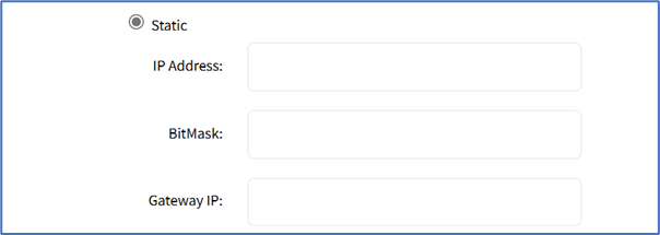
- Static radio button (if selected, expands dialog). Enter IP Address, BitMask, and (optional) Gateway IP.
- (optional) IPv4 DNS Server
- IPv4 DNS Search (defines a domain name for DNS lookups)
- IPv4 Default Route Metric
- Ignore obtained IPv4 Default Gateway checkbox
- Ignore obtained DNS server checkbox
- In IPv6 Mode menu, enter details:
- No IPv6 Address radio button
- Link local Only radio button.
- Address Auto Configuration radio button
- Stateful DHCPv6 radio button
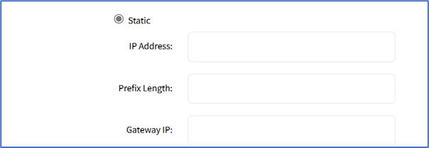
- (If Static radio button is selected, displays menu) Enter IP Address, Prefix Length, and (optional) Gateway IP.
- No IPv6 Address radio button
- (optional) IPv6 DNS Server
- IPv6 DNS Search (defines domain name for DNS lookups)
- IPv6 Default Route Metric
- Ignore obtained IPv6 Default Gateway checkbox
- Ignore obtained DNS server checkbox
- Click Save.