1. Introduction
This document describes how to run Palo Alto firewall Virtual Machines on a Nodegrid device, configure them in HA mode, and manage multiple VLANs bundled together in a trunk so that one firewall is down the other firewall takes over and the network connectivity is not lost.
You can use this setup to run any firewall on the Nodegrid device and use it as a gateway device to access the branch IT infrastructure.
Benefits
- Space Efficiency: Consolidating Palo Alto VMs on Nodegrid enables optimal space utilization, reducing the physical footprint of dedicated hardware appliances. This efficiency is particularly beneficial for organizations with limited rack space.
- Simplified Management: The unified setup on Nodegrid eliminates the need for managing disparate devices, and streamlining administrative tasks contributing to operational efficiency.
- Cost Saving: By running Palo Alto VMs on Nodegrid, the need for a physical firewall and additional routers and switches is eliminated, which results in cost savings and resource utilization.
2. Pre-requisites
Before you start with the deployment and configuration, ensure that you are familiar with the following procedures:
- How to create VLANs and Trunk links on Nodegrid and the connected switches. For more information, see Configuring VLAN and VLAN Trunks using a Nodegrid Device
- How to create virtual machines on Nodegrid. For more information, see:
- A secondary disk and knowledge of how to set up and configure a secondary storage disk on Nodegrid and use it for virtual machine storage
For more information, see Leading Practice for VM and Docker Storage Location on Nodegrid Nodegrid. - How to create network bridges on Nodegrid. For more information, see Configuration of a Bond interface and Bridge interfaces, How to Configure Network Bridge on the Nodegrid Serial Console
- How to configure and set the Palo Alto VM series. For more information, see Palo Alto documentation.
To access the referenced links, you may need to log in to the ZPE site.
3. Components Used
- ZPE Nodegrid Gate SR that runs Nodegrid OS Software Release 5.10.4 and above
- ZPE ZSW-228P 28-Port Switch that runs Firmware version 1.2.2.31 and above
3.1 Components That Can be Used Alternatively
This configuration can also be used with these hardware and software versions:
- ZPE Nodegrid Net SR that runs Nodegrid OS Software Release 5.10.4
- ZPE Nodegrid Net SR with switch expansion modules that run any of Nodegrid OS Software Release: 5.6.x, 5.8.x substitute 5.10.x for the layer 2 switches
- ZPE Nodegrid Gate that runs any of Nodegrid OS Software Release: 5.6.x, 5.8.x, 5.10.x can substitute for the layer 2 switches
- ZPE ZSW-228P 28-Port Switch that runs Firmware version 1.2.2.31 or greater
- Any third-party switch that supports VLANs and trunk VLAN links
4. Design Overview
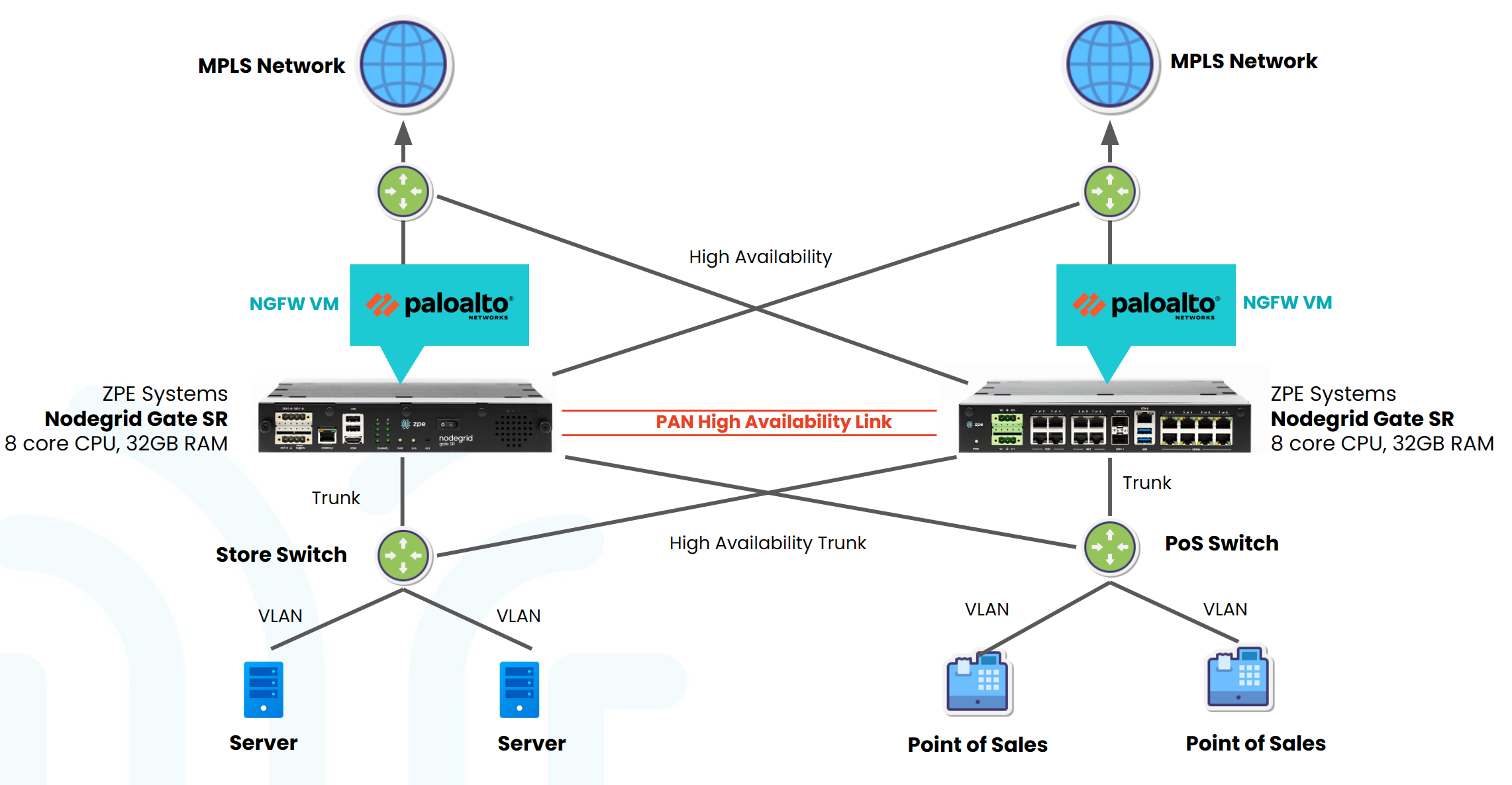
Before starting with the configuration, let us understand the network design involved in this setup. The network design provides a sample configuration to pair Palo Alto VMs in HA mode and provide internet access to networked devices from multiple VLANs.
The Network Design diagram illustrates a concise network configuration featuring access switches that are connected to Palo Alto VMs hosted on each NodegridGSR. Each access switch operates with two VLANs. Utilizing trunk links, these access switches efficiently channel network traffic upwards to the Palo Alto Firewalls. The Palo Alto Firewalls, in turn, seamlessly direct Internet traffic through one of two ISPs based on their availability.
4.1 Network Design
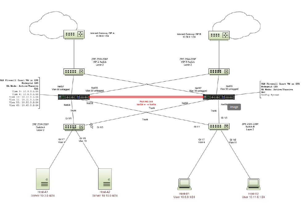
There are the ten VLANs defined:
- VLAN 3: Server Network 10.3.0.0/24
- VLAN 6: User Network 10.6.0.0/24
- VLAN 10: Server Network 10.10.0.0/24
- VLAN 11: User Network 10.11.0.0/24
- VLAN 50: WAN Traffic 10.50.0.0/24 - backup ISP via Internet Gateway ISP A
- VLAN 60: WAN Traffic 10.60.0.0/24 - primary ISP via Internet Gateway ISP B
- VLAN 100: HA1 Control Link
- VLAN 101: HA1 Control Link Backup
- VLAN 102: HA2 Data Link
- VLAN 103: HA2 Data Link Backup
These are the trunks used: - Trunk: VLANs 3, 10
- Trunk: VLANs 6, 11
- Trunk: VLANs 100, 101, 102, 103
The default gateway configuration on each server and host device must be the VLAN interface IP address that corresponds to the Palo Alto Firewall. The default route for the Palo Alto Firewall points to Internet Gateway ISP A, and Internet Gateway ISP B is the backup default route. The Palo Alto HA links are carried through a single trunk directly connected between the two Nodegrid GSRs.
4.2 Virtual Machine Network Breakout Diagram
The PAN Firewall virtual machine virtual NICs are connected to several network bridges on the Nodegrid GSR. The following diagram shows how they are connected and their purpose.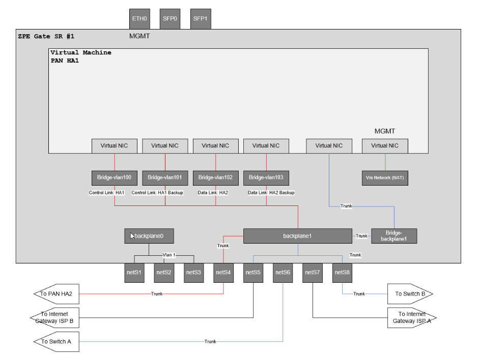
There are four virtual NICs. The 4 NICs are dedicated to the HA, VLAN trunks, Data Production Network, and Management Virtual NIC which GSR has access to. The diagram also shows how the backplanes are connected. Each physical port from NETS1 to NETS8 indicates where they are connected. For example, Nets4 is used to recognize the heartbeat, so that both the Nodegrid GSRs are connected.
4.3 Nodegrid GSR VLAN and Bridge Configuration
The tables in this section outline the VLAN and bridge configurations. This section highlights the Nodegrid VLAN and bridge configuration. The Interface name for each bridge varies depending on the order in which the bridges are created.
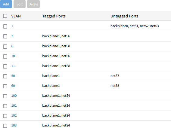
4.3.1 VLANs
Nodegrid Name | VLAN | Tagged Ports | Untagged Ports |
ZPE GSR-A | 3 | backplane1, netS6 | |
ZPE GSR-A | 6 | backplane1, netS8 | |
ZPE GSR-A | 10 | backplane1, netS6 | |
ZPE GSR-A | 11 | backplane1, netS8 | |
ZPE GSR-A | 50 | backplane1 | netS7 |
ZPE GSR-A | 60 | backplane1 | netS5 |
ZPE GSR-A | 100 | backplane1, netS4 | |
ZPE GSR-A | 101 | backplane1, netS4 | |
ZPE GSR-A | 102 | backplane1, netS4 | |
ZPE GSR-A | 103 | backplane1, netS4 | |
ZPE GSR-B | 3 | backplane1, netS6 | |
ZPE GSR-B | 6 | backplane1, netS8 | |
ZPE GSR-B | 10 | backplane1, netS6 | |
ZPE GSR-B | 11 | backplane1, netS8 | |
ZPE GSR-B | 50 | backplane1 | netS5 |
ZPE GSR-B | 60 | backplane1 | netS7 |
ZPE GSR-B | 100 | backplane1, netS4 | |
ZPE GSR-B | 101 | backplane1, netS4 | |
ZPE GSR-B | 102 | backplane1, netS4 | |
ZPE GSR-B | 103 | backplane1, netS4 |
4.3.2 Bridges
Nodegrid Name | Bridge Name | Bridged Interfaces | Interface | IPv4 Address |
ZPE GSR-A | BRDG-BACKPLANE1 | backplane1 | br0 | No Address |
ZPE GSR-A | BRDG-VL-100 | br0.100 | br1 | No Address |
ZPE GSR-A | BRDG-VL-101 | br0.101 | br2 | No Address |
ZPE GSR-A | BRDG-VL-102 | br0.102 | br3 | No Address |
ZPE GSR-A | BRDG-VL-103 | br0.103 | br4 | No Address |
ZPE GSR-B | BRDG-BACKPLANE1 | backplane1 | br0 | No Address |
ZPE GSR-B | BRDG-VL-100 | br0.100 | br1 | No Address |
ZPE GSR-B | BRDG-VL-101 | br0.101 | br2 | No Address |
ZPE GSR-B | BRDG-VL-102 | br0.102 | br3 | No Address |
ZPE GSR-B | BRDG-VL-103 | br0.103 | br4 | No Address |
4.4 Switch Configurations
- The switches ISP-A and ISP-B handle Internet traffic and their configurations are simple Layer 2 with no VLANs.
- The switches, Switch-A and Switch-B handle server and user traffic and are configured with the appropriate VLANs and trunks.
Switch Name | Interface | Switch Mode | VLANs | Tagged/Untagged |
Switch-A | e1/1 | trunk | 3,10 | Tagged |
Switch-A | e1/3 | trunk | 3,10 | Tagged |
Switch-A | e1/7 | access | 3 | Untagged |
Switch-A | e1/8 | access | 10 | Untagged |
Switch-B | e1/1 | trunk | 6,11 | Tagged |
Switch-B | e1/3 | trunk | 6,11 | Tagged |
Switch-B | e1/7 | access | 6 | Untagged |
Switch-B | e1/8 | access | 11 | Untagged |
4.5 Configurations
There are several configurations, four ZPE switches, two ZPE Nodegrid Gate SR, two VM configurations, and two PAN Firewall configurations.
For the configuration tasks outlined below, it is assumed the Nodegrids are starting from the factory default configuration and connected to the management network. The PAN Firewalls are also assumed to be starting from factory default.
Configuration Tasks Outline
- Configure Switches
- Uplink switches
- ISP-A Switch Layer 2: no vlans
- ISP-B Switch Layer 2: no vlans
- Downlink switches
- Switch-A Layer 2: VLANs and trunks
- Switch-B Layer 2: VLANs and trunks
- Uplink switches
- Configure Nodegrid Gate SR
- Create VLANs and VLAN trunks
- Create network bridges
- Create PAN Firewall VM
- Configure PAN Firewall
- Create virtual routers
- Create VLAN interfaces
- Create HA interfaces
- Enable and configure Active/Passive HA Mode
- Configure path monitoring failover to backup Internet Gateway
5. Step-by-Step Walkthrough
Deploying two Palo Alto VMs in HA mode with ZPE Nodegrid Gate Service Routers involves the following steps:
- Step 1: Configure ISP-A and ISB-B switches
- Step 2: Configure ZPE-GSR-A VLANs and Bridges
- Step 3: Configure ZPE-GSR-B VLANs and bridges
- Step 4: Install Palo Alto Virtual Machines
- Step 5: Configure Palo Alto VMs
Refer to configurations in the Appendix during the walkthrough.
Step 1: Configure ISP-A and ISB-B switches
These switches are configured as simple layer 2 switches with no VLANs.
Configure Switch-A
- Add the VLANs.
- Create two trunk ports for VLAN 3 and 10.
- Set two access ports for servers.
- Log in to the switch console and configure.
Console#configure Console(config)#vlan database

Console(config-vlan)#vlan 3 media ethernet Console(config-vlan)#vlan 10 media ethernet Console(config-vlan)#exit

Console(config)# Console(config)#interface ethernet 1/1

Console(config-if)#switchport mode trunk

Console(config-if)#switchport allowed vlan add 3,10 tagged Console(config-if)#switchport allowed vlan remove 1 Console(config-if)#switchport forbidden vlan add 1 Console(config-if)#exit

Console(config)# Console(config)#interface ethernet 1/3 Console(config-if)#switchport mode trunk

Console(config-if)#switchport allowed vlan add 3,10 tagged Console(config-if)#switchport allowed vlan remove 1 Console(config-if)#switchport forbidden vlan add 1 Console(config-if)#exit

Console(config)# Console(config)#interface ethernet 1/7 Console(config-if)#switchport mode access

Console(config-if)#switchport allowed vlan add 3 untagged Console(config-if)#switchport native vlan 3 Console(config-if)#switchport allowed vlan remove 1 Console(config-if)#exit

Console(config)# Console(config)#interface ethernet 1/8 Console(config-if)#switchport mode access

Console(config-if)#switchport allowed vlan add 10 untagged Console(config-if)#switchport native vlan 10 Console(config-if)#switchport allowed vlan remove 1 Console(config-if)#exit

Console(config)#
For detailed sample configuration, see the Appendix section.
Configure Switch-B
- Add the VLANs.
- Create two trunk ports for VLAN 6 and 11.
- Set two access ports for users.
- In the switch console, execute the following commands:
Console#configure Console(config)#vlan database

Console(config-vlan)#vlan 6 media ethernet Console(config-vlan)#vlan 11 media ethernet Console(config-vlan)#exit

Console(config)# Console(config)#interface ethernet 1/1 Console(config-if)#switchport mode trunk

Console(config-if)#switchport allowed vlan add 3,10 tagged Console(config-if)#switchport allowed vlan remove 1 Console(config-if)#switchport forbidden vlan add 1 Console(config-if)#exit

Console(config)# Console(config)#interface ethernet 1/3 Console(config-if)#switchport mode trunk

Console(config-if)#switchport allowed vlan add 3,10 tagged Console(config-if)#switchport allowed vlan remove 1 Console(config-if)#switchport forbidden vlan add 1 Console(config-if)#exit

Console(config)# Console(config)#interface ethernet 1/7 Console(config-if)#switchport mode access

Console(config-if)#switchport allowed vlan add 3 untagged Console(config-if)#switchport native vlan 3

Console(config-if)#switchport allowed vlan remove 1 Console(config-if)#exit

Console(config)# Console(config)#interface ethernet 1/8 Console(config-if)#switchport mode access

Console(config-if)#switchport allowed vlan add 10 untagged Console(config-if)#switchport native vlan 10 Console(config-if)#switchport allowed vlan remove 1 Console(config-if)#exit

Console(config)#
For detailed sample configuration, see the Appendix section.
Step 2: Configure ZPE-GSR-A VLANs and Bridges
The Nodegrid GSR hosts the active Palo Alto firewall in active/passive configuration. In this section, you will configure the VLANs and the bridges. The Nodegrid has two backplane interfaces to the switch, dedicate and utilize backplane1 for the PAN VM VLANs.
VLANs
- Go to Network::Switch::VLAN.
- Click Add to create the VLANs. Refer to the table VLANs in Nodegrid GSR VLAN and Bridge Configuration.
Bridges
- Create a bridge for backplane1 which feeds as a trunk ethernet port directly to the PAN.
- Create VLAN connections for each HA VLANs, these can not feed as an ethernet trunk to the PAN as ethernet type is not supported by PAN HA connections.
- For each HA VLANs, create a bridge and connect each directly to the PAN.
Perform the following actions to create these bridges:
- Navigate to Network::Connections
- On the Network Connections page, Click Add to create a bridge on backplane1. Enter the following details:
- Type = "Bridge"
- Bridge Interfaces = backplane1
- Spanning Tree Protocol = Disabled
- Ipv4 Mode = "No Ipv4 Address".
- Make a note of the bridge interface name is created. In this example, the interface name is br0
- On the Network Connections page, click Add to create a VLAN connection 100.
- Type = "VLAN"
- Interface = br0 (this is the bridge interface name created in step 2)
- Spanning Tree Protocol = Disabled
- Ipv4 Mode = "No Ipv4 Address".
- Make a note of the VLAN connection interface name. In this example, it is br0.100.
- Repeat for remaining VLANs 101, 102, 103.
- Create the VLAN bridges for each of VLAN 100 through 103, starting with 100.
- On the Network Connections page, Click Add.
- Type = "Bridge" Bridge
- Interfaces = br0.100
- Spanning Tree Protocol = Disabled
- Ipv4 Mode = "No Ipv4 Address"
- Make a note of the bridge interface name that is created. In this example, it is br1. Repeat for VLAN connections br0.101, br0.102, br0.103.
When completed, you will have a list of bridges as shown in the following image: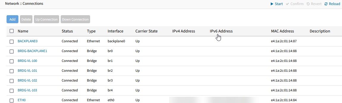
- On the Network Connections page, Click Add.
Step 3: Configure ZPE-GSR-B VLANs and bridges
In our example, the VLAN and bridge configuration is the same as ZPE-GSR-A.
Step 4: Install VM on Nodegrid Device
Prepare for the PAN VM Installation
- Prepare the secondary disk that will be used for the VM storage, follow the instructions mentioned in Leading Practice for VM and Docker Storage Location on Nodegrid
- Apply for Nodegrid VM license
- Enable VM service in Nodegrid
Import PAN VM
Importing the qcow2 will by default add a virtual NIC to the VM connected to the host-provided NAT network: 192.168.122.0/24.
This network is not accessible externally, however, it is accessible to the Nodegrid host and you will use this network for the Palo Alto Firewall VM management interface.
- Navigate to Applications::Virtual Machines, and choose Import VM:
- Name =[choose unique name]
- Disk Image =[path to your qcow2 image from PAN]
This will be the permanent location of the VM. Copy the master qcow2 file to the location you want as a permanent storage location. Typically, this would be: /var/lib/libvirt/images/[image name] - Operating System = Centos 7
- Memory =8GB(or custom size)
- Click Import and Run and let Palo Alto VM finish its installation.
- After the VM is fully up, the virtual NIC will obtain an IP from the NAT network, make a note of this. PAN VM will detect this as the first NIC and mark this as a management interface.
- Create a Managed Device connection for the PAN VM
- Select virtual_console_kvm.
- Select 'virtual_console_kvm'
- Name = [Name of VM] (this must match exactly the name of the VM you created)
- IP Address: 127.0.0.1
- Web URL: https://[ip of NAT interface]
- Mode: Enabled
- Select virtual_console_kvm.
When the Palo Alto VM is ready, click the Web button to log in to the Web management portal for the managed device connection that was created. Once logged into PAN successfully, shut down the system and connect the VM to the bridges.
Connecting the remaining network interfaces:
- Shut down the VM.
- Go to the Network section of the VM configuration.
- Add Network Interface for backplane1 bridge:
- Interface Type = Bridge to LAN
- Source = br0
- Model = virtio
- MAC Address =Generate(or choose a static assigned MAC address)
- Repeat for each of the HA bridges br1, br2, br3, br4
- Start the VM
VM network configuration will look similar to this:
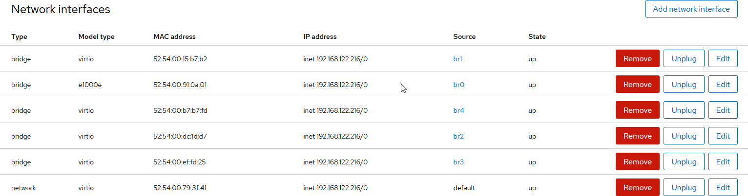
Once fully started, configure the Palo Alto VM interfaces, policies, nat, HA mode, and path monitoring from the management UI.
Step 5: Configure Palo Alto VMs
This part of the configuration steps is well documented at the Palo Alto documentation site as well as community guides and instructional videos. Refer to the following video guides and Palo Alto Documentation site for details:
- Palo Alto Techdocs
- (YouTube) Active Passive High Availability, Configuring HA - Palo Alto
- (YouTube) Palo Alto Path monitoring failover with Dual ISPs
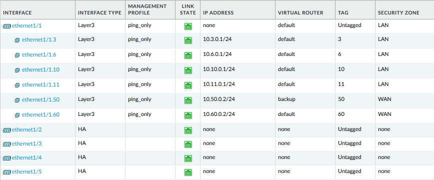
Configure the interfaces and policies
- Create a default virtual router for the main ISP-A.
- Identify the interface connected to the trunk bridge, br0 is the trunk bridge in this example, and set it as Layer 3.
- Create sub-interfaces for each VLAN.
- Create policies and NAT rules to allow access through the Internet via ISP-A.
- Configure Active/Passive HA mode.
- Identify the interfaces that are connected to each of the HA bridges and set them as HA.
- Set the HA parameters utilizing the HA link.
- Create a second virtual router for backup ISP-B.
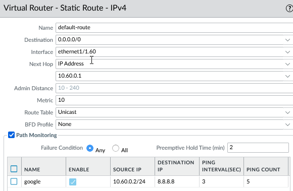
- Set static routes for each virtual router, default, and backup, as appropriate.
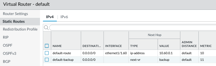
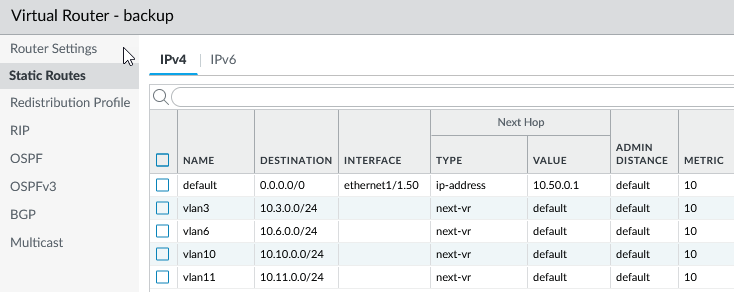
- Set path monitoring to failover to the backup virtual router.
Appendix A
ISP A Switch Configuration
!<stackingDB>00</stackingDB>
!<stackingMac>01_e4-9d-73-40-5b-3d_04</stackingMac>
!
hostname ISP-A-SWITCH
!
snmp-server community public ro
snmp-server community private rw
!
Finished
References
Appendix A
ISP A Switch Configuration
!
enable password 7 1b3231655cebb7a1f783eddf27d254ca
!
!
!
vlan database
VLAN 1 name DefaultVlan media ethernet
!
!
!
!
interface ethernet 1/1
!
interface ethernet 1/2
!
interface ethernet 1/3
!
interface ethernet 1/4
!
interface ethernet 1/5
!
interface ethernet 1/6
!
interface ethernet 1/7
!
interface ethernet 1/8
!
interface ethernet 1/9
!
interface ethernet 1/10
!
interface ethernet 1/11
!
interface ethernet 1/12
!
interface ethernet 1/13
!
interface ethernet 1/14
!
interface ethernet 1/15
!
interface ethernet 1/16
!
interface ethernet 1/17
!
interface ethernet 1/18
!
interface ethernet 1/19
!
interface ethernet 1/20
!
interface ethernet 1/21
!
interface ethernet 1/22
!
interface ethernet 1/23
!
interface ethernet 1/24
!
interface ethernet 1/25
!
interface ethernet 1/26
!
interface ethernet 1/27
!
interface ethernet 1/28
!
!
!
!
interface vlan 1
!
!
!
!
!
!
!
!
!
!
interface vlan 1
!
!
!
!
!
!
!
line console
!
!
line vty
!
!
!
end
!
ISP B Switch Configuration
!<stackingDB>00</stackingDB>
!<stackingMac>01_e4-9d-73-3b-46-9d_05</stackingMac>
!
hostname ISP-B-SWITCH
!
snmp-server community public ro
snmp-server community private rw
!
!
enable password 7 1b3231655cebb7a1f783eddf27d254ca
!
!
!
vlan database
VLAN 1 name DefaultVlan media ethernet
!
!
ISP B Switch Configuration
!
!
interface ethernet 1/1
!
interface ethernet 1/2
!
interface ethernet 1/3
!
interface ethernet 1/4
!
interface ethernet 1/5
!
interface ethernet 1/6
!
interface ethernet 1/7
!
interface ethernet 1/8
!
interface ethernet 1/9
!
interface ethernet 1/10
!
interface ethernet 1/11
!
interface ethernet 1/12
!
interface ethernet 1/13
!
interface ethernet 1/14
!
interface ethernet 1/15
!
interface ethernet 1/16
!
interface ethernet 1/17
!
interface ethernet 1/18
!
interface ethernet 1/19
!
interface ethernet 1/20
!
interface ethernet 1/21
!
interface ethernet 1/22
!
interface ethernet 1/23
!
interface ethernet 1/24
!
interface ethernet 1/25
!
interface ethernet 1/26
!
interface ethernet 1/27
!
interface ethernet 1/28
!
!
!
!
interface vlan 1
!
!
!
!
!
!
!
!
!
!
interface vlan 1
!
!
!
!
!
!
!
line console
!
!
line vty
!
!
!
end
!
Switch-A Configuration
!<stackingDB>00</stackingDB>
!<stackingMac>01_e4-9d-73-40-51-9d_04</stackingMac>
!
hostname SWITCH-A
!
!
snmp-server community public ro
snmp-server community private rw
!
!
enable password 7 1b3231655cebb7a1f783eddf27d254ca
!
!
vlan database
VLAN 1 name DefaultVlan media ethernet
vlan 3,10 media ethernet
!
!
interface ethernet 1/1
switchport mode trunk
switchport allowed vlan add 3,10 tagged
switchport allowed vlan remove 1
switchport forbidden vlan add 1
!
interface ethernet 1/2
!
Switch-A Configuration
interface ethernet 1/3
switchport mode trunk
switchport allowed vlan add 3,10 tagged
switchport allowed vlan remove 1
switchport forbidden vlan add 1
!
interface ethernet 1/4
!
interface ethernet 1/5
!
interface ethernet 1/6
!
interface ethernet 1/7
switchport allowed vlan add 3 untagged
switchport mode access
switchport native vlan 3
switchport allowed vlan remove 1
!
interface ethernet 1/8
switchport allowed vlan add 10 untagged
switchport mode access
switchport native vlan 10
switchport allowed vlan remove 1
!
interface ethernet 1/9
!
interface ethernet 1/10
!
interface ethernet 1/11
!
interface ethernet 1/12
!
interface ethernet 1/13
!
interface ethernet 1/14
!
interface ethernet 1/15
!
interface ethernet 1/16
!
interface ethernet 1/17
!
interface ethernet 1/18
!
interface ethernet 1/19
!
interface ethernet 1/20
!
interface ethernet 1/21
!
interface ethernet 1/22
!
interface ethernet 1/23
!
interface ethernet 1/24
!
interface ethernet 1/25
!
interface ethernet 1/26
!
interface ethernet 1/27
!
interface ethernet 1/28
!
!
!
!
!
interface vlan 1
!
!
!
!
!
!
!
!
!
!
!
!
!
interface vlan 1
!
!
!
!
!
!
!
line console
!
!
line vty
!
!
!
end
!
Switch-B Configuration
!<stackingDB>00</stackingDB>
!<stackingMac>01_e4-9d-73-40-51-9d_06</stackingMac>
!
hostname SWITCH-B
!
!
snmp-server community public ro
snmp-server community private rw
!
!
enable password 7 1b3231655cebb7a1f783eddf27d254ca
!
!
vlan database
VLAN 1 name DefaultVlan media ethernet
vlan 6,11 media ethernet
Switch-B Configuration
!
!
interface ethernet 1/1
switchport mode trunk
switchport allowed vlan add 6,11 tagged
switchport allowed vlan remove 1
switchport forbidden vlan add 1
!
interface ethernet 1/2
!
interface ethernet 1/3
switchport mode trunk
switchport allowed vlan add 6,11 tagged
switchport allowed vlan remove 1
switchport forbidden vlan add 1
!
interface ethernet 1/4
!
interface ethernet 1/5
!
interface ethernet 1/6
!
interface ethernet 1/7
switchport allowed vlan add 6 untagged
switchport mode access
switchport native vlan 6
switchport allowed vlan remove 1
!
interface ethernet 1/8
switchport allowed vlan add 11 untagged
switchport mode access
switchport native vlan 11
switchport allowed vlan remove 1
!
interface ethernet 1/9
!
interface ethernet 1/10
!
interface ethernet 1/11
!
interface ethernet 1/12
!
interface ethernet 1/13
!
interface ethernet 1/14
!
interface ethernet 1/15
!
interface ethernet 1/16
!
interface ethernet 1/17
!
interface ethernet 1/18
!
interface ethernet 1/19
!
interface ethernet 1/20
!
interface ethernet 1/21
!
interface ethernet 1/22
!
interface ethernet 1/23
!
interface ethernet 1/24
!
interface ethernet 1/25
!
interface ethernet 1/26
!
interface ethernet 1/27
!
interface ethernet 1/28
!
!
!
!
!
interface vlan 1
!
!
!
!
!
!
!
!
!
!
!
!
!
interface vlan 1
!
!
!
!
!
!
!
line console
!
!
line vty
!
!
!
end
!
Nodegrid GSR-A Configuration
This listing only shows the relevant configurations needed. Comments preceded by # are added, note that comments are not supported as part of a CLI import.
# This section defines a managed device connection that connects
# to the Palo Alto virtual machine
Nodegrid GSR-A Configuration
/settings/devices/PA-VM1/access name=PA-VM1
/settings/devices/PA-VM1/access type=virtual_console_kvm
/settings/devices/PA-VM1/access ip_address=127.0.0.1
/settings/devices/PA-VM1/access web_url=https://192.168.122.54
/settings/devices/PA-VM1/access launch_url_via_html5=yes
/settings/devices/PA-VM1/access method=browser_extension_forwarder
/settings/devices/PA-VM1/access credential=set_now
/settings/devices/PA-VM1/access password=********
/settings/devices/PA-VM1/access allow_pre-shared_ssh_key=no
/settings/devices/PA-VM1/access enable_device_state_detection_based_on_network_traffic=no
/settings/devices/PA-VM1/access multisession=yes
/settings/devices/PA-VM1/access read-write_multisession=no
/settings/devices/PA-VM1/access enable_send_break=no
/settings/devices/PA-VM1/access icon=paloaltofirewall.png
/settings/devices/PA-VM1/access mode=enabled
/settings/devices/PA-VM1/access expiration=never
/settings/devices/PA-VM1/access end_point=appliance
/settings/devices/PA-VM1/access skip_authentication_to_access_device=no
/settings/devices/PA-VM1/access escape_sequence=^Ec
/settings/devices/PA-VM1/access power_control_key=^O
/settings/devices/PA-VM1/access show_text_information=yes
/settings/devices/PA-VM1/access enable_ip_alias=no
/settings/devices/PA-VM1/access enable_second_ip_alias=no
/settings/devices/PA-VM1/access allow_ssh_protocol=yes
/settings/devices/PA-VM1/access allow_telnet_protocol=no
/settings/devices/PA-VM1/access allow_binary_socket=no
/settings/devices/PA-VM1/management ssh_and_telnet=yes
/settings/devices/PA-VM1/management credential=use_specific
/settings/devices/PA-VM1/management password=********
/settings/devices/PA-VM1/management monitoring_nominal=no
/settings/devices/PA-VM1/logging data_logging=no
/settings/devices/PA-VM1/commands/console command=console
/settings/devices/PA-VM1/commands/console enabled=yes
/settings/devices/PA-VM1/commands/console launch_local_application=yes
/settings/devices/PA-VM1/commands/data_logging command=data_logging
/settings/devices/PA-VM1/commands/data_logging enabled=no
/settings/devices/PA-VM1/commands/mks command=mks
/settings/devices/PA-VM1/commands/mks enabled=yes
/settings/devices/PA-VM1/commands/mks vnc_password=********
/settings/devices/PA-VM1/commands/power command=power
/settings/devices/PA-VM1/commands/power enabled=yes
/settings/devices/PA-VM1/commands/web command=web
/settings/devices/PA-VM1/commands/web enabled=yes
/settings/devices/PA-VM1/commands/web web_url=https://192.168.122.54
# Network Bridges are defined here
/settings/network_connections/BRDG-BACKPLANE1 name=BRDG-BACKPLANE1
/settings/network_connections/BRDG-BACKPLANE1 type=bridge
/settings/network_connections/BRDG-BACKPLANE1 connect_automatically=yes
/settings/network_connections/BRDG-BACKPLANE1 set_as_primary_connection=no
/settings/network_connections/BRDG-BACKPLANE1 block_unsolicited_incoming_packets=no
/settings/network_connections/BRDG-BACKPLANE1 bridge_interfaces=backplane1
/settings/network_connections/BRDG-BACKPLANE1 bridge_mac_configuration=use_mac_from_first_interface
/settings/network_connections/BRDG-BACKPLANE1 enable_spanning_tree_protocol=no
/settings/network_connections/BRDG-BACKPLANE1 hello_time=2
/settings/network_connections/BRDG-BACKPLANE1 forward_delay=5
/settings/network_connections/BRDG-BACKPLANE1 max_age=20
/settings/network_connections/BRDG-BACKPLANE1 ageing_time=300
/settings/network_connections/BRDG-BACKPLANE1 ipv4_mode=no_ipv4_address
/settings/network_connections/BRDG-BACKPLANE1 ipv4_default_route_metric=425
/settings/network_connections/BRDG-BACKPLANE1 ipv4_ignore_obtained_default_gateway=no
/settings/network_connections/BRDG-BACKPLANE1 ipv4_ignore_obtained_dns_server=no
/settings/network_connections/BRDG-BACKPLANE1 ipv6_mode=no_ipv6_address
/settings/network_connections/BRDG-BACKPLANE1 ipv6_ignore_obtained_default_gateway=no
/settings/network_connections/BRDG-BACKPLANE1 ipv6_ignore_obtained_dns_server=no
/settings/network_connections/BRDG-VL-100 name=BRDG-VL-100
/settings/network_connections/BRDG-VL-100 type=bridge
/settings/network_connections/BRDG-VL-100 connect_automatically=yes
/settings/network_connections/BRDG-VL-100 set_as_primary_connection=no
/settings/network_connections/BRDG-VL-100 block_unsolicited_incoming_packets=no
/settings/network_connections/BRDG-VL-100 bridge_interfaces=br3.100
/settings/network_connections/BRDG-VL-100 bridge_mac_configuration=use_mac_from_first_interface
/settings/network_connections/BRDG-VL-100 enable_spanning_tree_protocol=yes
/settings/network_connections/BRDG-VL-100 hello_time=2
/settings/network_connections/BRDG-VL-100 forward_delay=5
/settings/network_connections/BRDG-VL-100 max_age=20
/settings/network_connections/BRDG-VL-100 ageing_time=300
/settings/network_connections/BRDG-VL-100 ipv4_mode=no_ipv4_address
/settings/network_connections/BRDG-VL-100 ipv4_default_route_metric=425
/settings/network_connections/BRDG-VL-100 ipv4_ignore_obtained_default_gateway=no
/settings/network_connections/BRDG-VL-100 ipv4_ignore_obtained_dns_server=no
/settings/network_connections/BRDG-VL-100 ipv6_mode=no_ipv6_address
/settings/network_connections/BRDG-VL-100 ipv6_ignore_obtained_default_gateway=no
/settings/network_connections/BRDG-VL-100 ipv6_ignore_obtained_dns_server=no
/settings/network_connections/BRDG-VL-101 name=BRDG-VL-101
/settings/network_connections/BRDG-VL-101 type=bridge
/settings/network_connections/BRDG-VL-101 connect_automatically=yes
/settings/network_connections/BRDG-VL-101 set_as_primary_connection=no
/settings/network_connections/BRDG-VL-101 block_unsolicited_incoming_packets=no
/settings/network_connections/BRDG-VL-101 bridge_interfaces=br3.101
/settings/network_connections/BRDG-VL-101 bridge_mac_configuration=use_mac_from_first_interface
/settings/network_connections/BRDG-VL-101 enable_spanning_tree_protocol=yes
/settings/network_connections/BRDG-VL-101 hello_time=2
/settings/network_connections/BRDG-VL-101 forward_delay=5
/settings/network_connections/BRDG-VL-101 max_age=20
/settings/network_connections/BRDG-VL-101 ageing_time=300
/settings/network_connections/BRDG-VL-101 ipv4_mode=no_ipv4_address
/settings/network_connections/BRDG-VL-101 ipv4_default_route_metric=425
/settings/network_connections/BRDG-VL-101 ipv4_ignore_obtained_default_gateway=no
/settings/network_connections/BRDG-VL-101 ipv4_ignore_obtained_dns_server=no
/settings/network_connections/BRDG-VL-101 ipv6_mode=no_ipv6_address
/settings/network_connections/BRDG-VL-101 ipv6_ignore_obtained_default_gateway=no
/settings/network_connections/BRDG-VL-101 ipv6_ignore_obtained_dns_server=no
/settings/network_connections/BRDG-VL-102 name=BRDG-VL-102
/settings/network_connections/BRDG-VL-102 type=bridge
/settings/network_connections/BRDG-VL-102 connect_automatically=yes
/settings/network_connections/BRDG-VL-102 set_as_primary_connection=no
/settings/network_connections/BRDG-VL-102 block_unsolicited_incoming_packets=no
/settings/network_connections/BRDG-VL-102 bridge_interfaces=br3.102
/settings/network_connections/BRDG-VL-102 bridge_mac_configuration=use_mac_from_first_interface
/settings/network_connections/BRDG-VL-102 enable_spanning_tree_protocol=yes
/settings/network_connections/BRDG-VL-102 hello_time=2
/settings/network_connections/BRDG-VL-102 forward_delay=5
/settings/network_connections/BRDG-VL-102 max_age=20
/settings/network_connections/BRDG-VL-102 ageing_time=300
/settings/network_connections/BRDG-VL-102 ipv4_mode=no_ipv4_address
/settings/network_connections/BRDG-VL-102 ipv4_default_route_metric=425
/settings/network_connections/BRDG-VL-102 ipv4_ignore_obtained_default_gateway=no
/settings/network_connections/BRDG-VL-102 ipv4_ignore_obtained_dns_server=no
/settings/network_connections/BRDG-VL-102 ipv6_mode=no_ipv6_address
/settings/network_connections/BRDG-VL-102 ipv6_ignore_obtained_default_gateway=no
/settings/network_connections/BRDG-VL-102 ipv6_ignore_obtained_dns_server=no
/settings/network_connections/BRDG-VL-103 name=BRDG-VL-103
/settings/network_connections/BRDG-VL-103 type=bridge
/settings/network_connections/BRDG-VL-103 connect_automatically=yes
/settings/network_connections/BRDG-VL-103 set_as_primary_connection=no
/settings/network_connections/BRDG-VL-103 block_unsolicited_incoming_packets=no
/settings/network_connections/BRDG-VL-103 bridge_interfaces=br3.103
/settings/network_connections/BRDG-VL-103 bridge_mac_configuration=use_mac_from_first_interface
/settings/network_connections/BRDG-VL-103 enable_spanning_tree_protocol=yes
/settings/network_connections/BRDG-VL-103 hello_time=2
/settings/network_connections/BRDG-VL-103 forward_delay=5
/settings/network_connections/BRDG-VL-103 max_age=20
/settings/network_connections/BRDG-VL-103 ageing_time=300
/settings/network_connections/BRDG-VL-103 ipv4_mode=no_ipv4_address
/settings/network_connections/BRDG-VL-103 ipv4_default_route_metric=425
/settings/network_connections/BRDG-VL-103 ipv4_ignore_obtained_default_gateway=no
/settings/network_connections/BRDG-VL-103 ipv4_ignore_obtained_dns_server=no
/settings/network_connections/BRDG-VL-103 ipv6_mode=no_ipv6_address
/settings/network_connections/BRDG-VL-103 ipv6_ignore_obtained_default_gateway=no
/settings/network_connections/BRDG-VL-103 ipv6_ignore_obtained_dns_server=no
# This is our management port, other ports can be used as management such as SFP0, SFP1
/settings/network_connections/ETH0 name=ETH0
/settings/network_connections/ETH0 type=ethernet
/settings/network_connections/ETH0 connect_automatically=yes
/settings/network_connections/ETH0 set_as_primary_connection=yes
/settings/network_connections/ETH0 enable_lldp=no
/settings/network_connections/ETH0 block_unsolicited_incoming_packets=no
/settings/network_connections/ETH0 ethernet_link_mode=auto
/settings/network_connections/ETH0 enable_ip_passthrough=no
/settings/network_connections/ETH0 ipv4_mode=static
/settings/network_connections/ETH0 ipv4_address=172.16.74.11
/settings/network_connections/ETH0 ipv4_bitmask=28
/settings/network_connections/ETH0 ipv4_gateway=172.16.74.1
/settings/network_connections/ETH0 ipv4_dns_server=8.8.8.8
/settings/network_connections/ETH0 ipv4_default_route_metric=90
/settings/network_connections/ETH0 ipv4_ignore_obtained_default_gateway=no
/settings/network_connections/ETH0 ipv4_ignore_obtained_dns_server=no
/settings/network_connections/ETH0 ipv6_mode=address_auto_configuration
/settings/network_connections/ETH0 ipv6_default_route_metric=90
/settings/network_connections/ETH0 ipv6_ignore_obtained_default_gateway=no
/settings/network_connections/ETH0 ipv6_ignore_obtained_dns_server=no
# Vlans and vlan trunks are configured in this section
/settings/switch_vlan/1 vlan=1
/settings/switch_vlan/1 untagged_ports=backplane0,netS1,netS2,netS3
/settings/switch_vlan/3 vlan=3
/settings/switch_vlan/3 tagged_ports=backplane1,netS6
/settings/switch_vlan/6 vlan=6
/settings/switch_vlan/6 tagged_ports=backplane1,netS8
/settings/switch_vlan/10 vlan=10
/settings/switch_vlan/10 tagged_ports=backplane1,netS6
/settings/switch_vlan/11 vlan=11
/settings/switch_vlan/11 tagged_ports=backplane1,netS8
/settings/switch_vlan/50 vlan=50
/settings/switch_vlan/50 tagged_ports=backplane1
/settings/switch_vlan/50 untagged_ports=netS7
/settings/switch_vlan/60 vlan=60
/settings/switch_vlan/60 tagged_ports=backplane1
/settings/switch_vlan/60 untagged_ports=netS5
/settings/switch_vlan/100 vlan=100
/settings/switch_vlan/100 tagged_ports=backplane1,netS4
/settings/switch_vlan/101 vlan=101
/settings/switch_vlan/101 tagged_ports=backplane1,netS4
/settings/switch_vlan/102 vlan=102
/settings/switch_vlan/102 tagged_ports=backplane1,netS4
/settings/switch_vlan/103 vlan=103
/settings/switch_vlan/103 tagged_ports=backplane1,netS4
# Virtual machine support is enabled here.
/settings/services enable_qemu|kvm=yes
Nodegrid GSR-B Configuration
This listing only shows the relevant configurations needed. Comments preceded by # are added, note that comments are not supported as part of a CLI import.
# This section defines a managed device connection that connects
# to the Palo Alto virtual machine
/settings/devices/PA-VM2/access name=PA-VM2
/settings/devices/PA-VM2/access type=virtual_console_kvm
/settings/devices/PA-VM2/access ip_address=127.0.0.1
/settings/devices/PA-VM2/access web_url=https://192.168.122.216
/settings/devices/PA-VM2/access launch_url_via_html5=yes
/settings/devices/PA-VM2/access method=browser_extension_forwarder
/settings/devices/PA-VM2/access credential=set_now
/settings/devices/PA-VM2/access password=********
/settings/devices/PA-VM2/access allow_pre-shared_ssh_key=no
/settings/devices/PA-VM2/access enable_device_state_detection_based_on_network_traffic=no
/settings/devices/PA-VM2/access multisession=yes
/settings/devices/PA-VM2/access read-write_multisession=no
/settings/devices/PA-VM2/access enable_send_break=no
/settings/devices/PA-VM2/access icon=terminal.png
/settings/devices/PA-VM2/access mode=enabled
/settings/devices/PA-VM2/access expiration=never
/settings/devices/PA-VM2/access end_point=appliance
/settings/devices/PA-VM2/access skip_authentication_to_access_device=no
/settings/devices/PA-VM2/access escape_sequence=^Ec
/settings/devices/PA-VM2/access power_control_key=^O
/settings/devices/PA-VM2/access show_text_information=yes
/settings/devices/PA-VM2/access enable_ip_alias=no
/settings/devices/PA-VM2/access enable_second_ip_alias=no
/settings/devices/PA-VM2/access allow_ssh_protocol=yes
/settings/devices/PA-VM2/access allow_telnet_protocol=no
/settings/devices/PA-VM2/access allow_binary_socket=no
/settings/devices/PA-VM2/management ssh_and_telnet=yes
/settings/devices/PA-VM2/management credential=use_specific
/settings/devices/PA-VM2/management password=********
Nodegrid GSR-B Configuration
/settings/devices/PA-VM2/management monitoring_nominal=no
/settings/devices/PA-VM2/logging data_logging=no
/settings/devices/PA-VM2/commands/console command=console
/settings/devices/PA-VM2/commands/console enabled=yes
/settings/devices/PA-VM2/commands/console launch_local_application=no
/settings/devices/PA-VM2/commands/data_logging command=data_logging
/settings/devices/PA-VM2/commands/data_logging enabled=no
/settings/devices/PA-VM2/commands/mks command=mks
/settings/devices/PA-VM2/commands/mks enabled=yes
/settings/devices/PA-VM2/commands/mks vnc_password=********
/settings/devices/PA-VM2/commands/power command=power
/settings/devices/PA-VM2/commands/power enabled=yes
/settings/devices/PA-VM2/commands/web command=web
/settings/devices/PA-VM2/commands/web enabled=yes
/settings/devices/PA-VM2/commands/web web_url=https://192.168.122.216
# Network Bridges are defined here
/settings/network_connections/BRDG-BACKPLANE1 name=BRDG-BACKPLANE1
/settings/network_connections/BRDG-BACKPLANE1 type=bridge
/settings/network_connections/BRDG-BACKPLANE1 connect_automatically=yes
/settings/network_connections/BRDG-BACKPLANE1 set_as_primary_connection=no
/settings/network_connections/BRDG-BACKPLANE1 block_unsolicited_incoming_packets=no
/settings/network_connections/BRDG-BACKPLANE1 bridge_interfaces=backplane1
/settings/network_connections/BRDG-BACKPLANE1 bridge_mac_configuration=use_mac_from_first_interface
/settings/network_connections/BRDG-BACKPLANE1 enable_spanning_tree_protocol=no
/settings/network_connections/BRDG-BACKPLANE1 hello_time=2
/settings/network_connections/BRDG-BACKPLANE1 forward_delay=5
/settings/network_connections/BRDG-BACKPLANE1 max_age=20
/settings/network_connections/BRDG-BACKPLANE1 ageing_time=300
/settings/network_connections/BRDG-BACKPLANE1 ipv4_mode=no_ipv4_address
/settings/network_connections/BRDG-BACKPLANE1 ipv4_default_route_metric=425
/settings/network_connections/BRDG-BACKPLANE1 ipv4_ignore_obtained_default_gateway=no
/settings/network_connections/BRDG-BACKPLANE1 ipv4_ignore_obtained_dns_server=no
/settings/network_connections/BRDG-BACKPLANE1 ipv6_mode=no_ipv6_address
/settings/network_connections/BRDG-BACKPLANE1 ipv6_ignore_obtained_default_gateway=no
/settings/network_connections/BRDG-BACKPLANE1 ipv6_ignore_obtained_dns_server=no
/settings/network_connections/BRDG-VL-100 name=BRDG-VL-100
/settings/network_connections/BRDG-VL-100 type=bridge
/settings/network_connections/BRDG-VL-100 connect_automatically=yes
/settings/network_connections/BRDG-VL-100 set_as_primary_connection=no
/settings/network_connections/BRDG-VL-100 block_unsolicited_incoming_packets=no
/settings/network_connections/BRDG-VL-100 bridge_interfaces=br0.100
/settings/network_connections/BRDG-VL-100 bridge_mac_configuration=use_mac_from_first_interface
/settings/network_connections/BRDG-VL-100 enable_spanning_tree_protocol=yes
/settings/network_connections/BRDG-VL-100 hello_time=2
/settings/network_connections/BRDG-VL-100 forward_delay=5
/settings/network_connections/BRDG-VL-100 max_age=20
/settings/network_connections/BRDG-VL-100 ageing_time=300
/settings/network_connections/BRDG-VL-100 ipv4_mode=no_ipv4_address
/settings/network_connections/BRDG-VL-100 ipv4_default_route_metric=425
/settings/network_connections/BRDG-VL-100 ipv4_ignore_obtained_default_gateway=no
/settings/network_connections/BRDG-VL-100 ipv4_ignore_obtained_dns_server=no
/settings/network_connections/BRDG-VL-100 ipv6_mode=no_ipv6_address
/settings/network_connections/BRDG-VL-100 ipv6_ignore_obtained_default_gateway=no
/settings/network_connections/BRDG-VL-100 ipv6_ignore_obtained_dns_server=no
/settings/network_connections/BRDG-VL-101 name=BRDG-VL-101
/settings/network_connections/BRDG-VL-101 type=bridge
/settings/network_connections/BRDG-VL-101 connect_automatically=yes
/settings/network_connections/BRDG-VL-101 set_as_primary_connection=no
/settings/network_connections/BRDG-VL-101 block_unsolicited_incoming_packets=no
/settings/network_connections/BRDG-VL-101 bridge_interfaces=br0.101
/settings/network_connections/BRDG-VL-101 bridge_mac_configuration=use_mac_from_first_interface
/settings/network_connections/BRDG-VL-101 enable_spanning_tree_protocol=yes
/settings/network_connections/BRDG-VL-101 hello_time=2
/settings/network_connections/BRDG-VL-101 forward_delay=5
/settings/network_connections/BRDG-VL-101 max_age=20
/settings/network_connections/BRDG-VL-101 ageing_time=300
/settings/network_connections/BRDG-VL-101 ipv4_mode=no_ipv4_address
/settings/network_connections/BRDG-VL-101 ipv4_default_route_metric=425
/settings/network_connections/BRDG-VL-101 ipv4_ignore_obtained_default_gateway=no
/settings/network_connections/BRDG-VL-101 ipv4_ignore_obtained_dns_server=no
/settings/network_connections/BRDG-VL-101 ipv6_mode=no_ipv6_address
/settings/network_connections/BRDG-VL-101 ipv6_ignore_obtained_default_gateway=no
/settings/network_connections/BRDG-VL-101 ipv6_ignore_obtained_dns_server=no
/settings/network_connections/BRDG-VL-102 name=BRDG-VL-102
/settings/network_connections/BRDG-VL-102 type=bridge
/settings/network_connections/BRDG-VL-102 connect_automatically=yes
/settings/network_connections/BRDG-VL-102 set_as_primary_connection=no
/settings/network_connections/BRDG-VL-102 block_unsolicited_incoming_packets=no
/settings/network_connections/BRDG-VL-102 bridge_interfaces=br0.102
/settings/network_connections/BRDG-VL-102 bridge_mac_configuration=use_mac_from_first_interface
/settings/network_connections/BRDG-VL-102 enable_spanning_tree_protocol=yes
/settings/network_connections/BRDG-VL-102 hello_time=2
/settings/network_connections/BRDG-VL-102 forward_delay=5
/settings/network_connections/BRDG-VL-102 max_age=20
/settings/network_connections/BRDG-VL-102 ageing_time=300
/settings/network_connections/BRDG-VL-102 ipv4_mode=no_ipv4_address
/settings/network_connections/BRDG-VL-102 ipv4_default_route_metric=425
/settings/network_connections/BRDG-VL-102 ipv4_ignore_obtained_default_gateway=no
/settings/network_connections/BRDG-VL-102 ipv4_ignore_obtained_dns_server=no
/settings/network_connections/BRDG-VL-102 ipv6_mode=no_ipv6_address
/settings/network_connections/BRDG-VL-102 ipv6_ignore_obtained_default_gateway=no
/settings/network_connections/BRDG-VL-102 ipv6_ignore_obtained_dns_server=no
/settings/network_connections/BRDG-VL-103 name=BRDG-VL-103
/settings/network_connections/BRDG-VL-103 type=bridge
/settings/network_connections/BRDG-VL-103 connect_automatically=yes
/settings/network_connections/BRDG-VL-103 set_as_primary_connection=no
/settings/network_connections/BRDG-VL-103 block_unsolicited_incoming_packets=no
/settings/network_connections/BRDG-VL-103 bridge_interfaces=br0.103
/settings/network_connections/BRDG-VL-103 bridge_mac_configuration=use_mac_from_first_interface
/settings/network_connections/BRDG-VL-103 enable_spanning_tree_protocol=yes
/settings/network_connections/BRDG-VL-103 hello_time=2
/settings/network_connections/BRDG-VL-103 forward_delay=5
/settings/network_connections/BRDG-VL-103 max_age=20
/settings/network_connections/BRDG-VL-103 ageing_time=300
/settings/network_connections/BRDG-VL-103 ipv4_mode=no_ipv4_address
/settings/network_connections/BRDG-VL-103 ipv4_default_route_metric=425
/settings/network_connections/BRDG-VL-103 ipv4_ignore_obtained_default_gateway=no
/settings/network_connections/BRDG-VL-103 ipv4_ignore_obtained_dns_server=no
/settings/network_connections/BRDG-VL-103 ipv6_mode=no_ipv6_address
/settings/network_connections/BRDG-VL-103 ipv6_ignore_obtained_default_gateway=no
/settings/network_connections/BRDG-VL-103 ipv6_ignore_obtained_dns_server=no
# This is our management port, other ports can be used as management such as SFP0, SFP1
/settings/network_connections/ETH0 name=ETH0
/settings/network_connections/ETH0 type=ethernet
/settings/network_connections/ETH0 connect_automatically=yes
/settings/network_connections/ETH0 set_as_primary_connection=yes
/settings/network_connections/ETH0 enable_lldp=yes
/settings/network_connections/ETH0 port_id=interface_name
/settings/network_connections/ETH0 port_description=interface_description
/settings/network_connections/ETH0 block_unsolicited_incoming_packets=no
/settings/network_connections/ETH0 ethernet_link_mode=auto
/settings/network_connections/ETH0 enable_ip_passthrough=no
/settings/network_connections/ETH0 ipv4_mode=static
/settings/network_connections/ETH0 ipv4_address=172.16.74.12
/settings/network_connections/ETH0 ipv4_bitmask=28
/settings/network_connections/ETH0 ipv4_gateway=172.16.74.1
/settings/network_connections/ETH0 ipv4_dns_server=8.8.8.8
/settings/network_connections/ETH0 ipv4_default_route_metric=90
/settings/network_connections/ETH0 ipv4_ignore_obtained_default_gateway=no
/settings/network_connections/ETH0 ipv4_ignore_obtained_dns_server=no
/settings/network_connections/ETH0 ipv6_mode=address_auto_configuration
/settings/network_connections/ETH0 ipv6_default_route_metric=90
/settings/network_connections/ETH0 ipv6_ignore_obtained_default_gateway=no
/settings/network_connections/ETH0 ipv6_ignore_obtained_dns_server=no
# Vlans and vlan trunks are configured in this section
/settings/switch_vlan/1 vlan=1
/settings/switch_vlan/1 untagged_ports=backplane0,netS1,netS2,netS3
/settings/switch_vlan/3 vlan=3
/settings/switch_vlan/3 tagged_ports=backplane1,netS6
/settings/switch_vlan/6 vlan=6
/settings/switch_vlan/6 tagged_ports=backplane1,netS8
/settings/switch_vlan/10 vlan=10
/settings/switch_vlan/10 tagged_ports=backplane1,netS6
/settings/switch_vlan/11 vlan=11
/settings/switch_vlan/11 tagged_ports=backplane1,netS8
/settings/switch_vlan/50 vlan=50
/settings/switch_vlan/50 tagged_ports=backplane1
/settings/switch_vlan/50 untagged_ports=netS5
/settings/switch_vlan/60 vlan=60
/settings/switch_vlan/60 tagged_ports=backplane1
/settings/switch_vlan/60 untagged_ports=netS7
/settings/switch_vlan/100 vlan=100
/settings/switch_vlan/100 tagged_ports=backplane1,netS4
/settings/switch_vlan/101 vlan=101
/settings/switch_vlan/101 tagged_ports=backplane1,netS4
/settings/switch_vlan/102 vlan=102
/settings/switch_vlan/102 tagged_ports=backplane1,netS4
/settings/switch_vlan/103 vlan=103
/settings/switch_vlan/103 tagged_ports=backplane1,netS4
# Virtual machine support is enabled here
/settings/services enable_qemu|kvm=yes