How to Create a Site-to-Site VPN/Overlay Network using Wireguard
Wireguard supports a wide range of overlay architecture designs. The most common architecture used with Nodegrid is the Server-Client architecture, which supports host-to-host and site-to-site communication. Wireguard does not directly differentiate between clients and servers. The main difference is that a server actively listens for incoming connections on a specified UDP port.
Another aspect that must be mentioned is the native support for roaming connections, which sets Wireguard apart from other VPN technologies like IPSec and OpenVPN. Wireguard sessions are not bound to a specific interface or network on either the client or the server site. Tunnels can dynamically change interfaces and networks without closing the session. This process is supported from both ends by dynamically updating the other side over changing endpoint details, like roaming IP Addresses or dynamically assigned ports. The result is a dynamic failover of the overlay network without impact on existing sessions or the need to re-establish connections which utilize the tunnel.
Routing
For a site-to-site VPN/Overlay design, is it required to enable routing on each device in the Network Settings tab.
Nodegrid OS supports more advanced routing options, including dynamic routing, for example, BGP and OSPF.
Please contact support for more details and guidance.
Overview
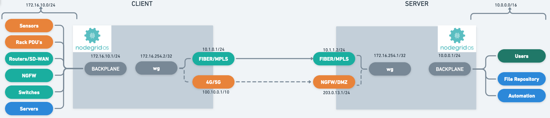
The guide uses the following network layout as an example configuration.
Quick Step-by-step Walkthrough
Server-Side:
Configure a Server Configuration under Network :: VPN :: Wireguard
Take note of the server's public key
Repeat the following steps for each Client
Client Side:
Configure a Client Configuration under Network :: VPN drop-down :: Wireguard
Take note of the client's public key
Configure the server as a peer in the Client Configuration under Network :: VPN drop-down :: Wireguard :: <CLIENT CONFIGURATION>
Provide the Public IP, Port, and public key of the server
Server-Side:
Configure the client as a peer in the Server Configuration under Network :: VPN drop-down :: Wireguard :: <SERVER CONFIGURATION>
public key of the client
Server-Side Configuration
Server-side configuration is most commonly done on Nodegrid appliances, which act as central access points or VPN concentrators. Typically, these are Nodegrid VSR (Virtual Service Router) or NetSR appliances hosted in a Data Center or Public Cloud.
A Nodegrid instance can handle multiple Server configurations at the same time. This allows for traffic separation, for example, separation of Nodegrid to Nodegrid communication and User to Nodegrid configuration and more.
Server Interface Configuration
This part of the configuration is only required once for each overlay network. The configuration creates a server interface and allows them to authorize clients to connect to the server configuration.
To configure a server interface, use the following steps (for a full list of options, look here):
Go to the Network :: VPN :: Wireguard page
Click Add (opens dialog)
Enter an Interface Name (Example: EMEA); this name is used for the network interface
From the Interface Type drop-down list, select Server
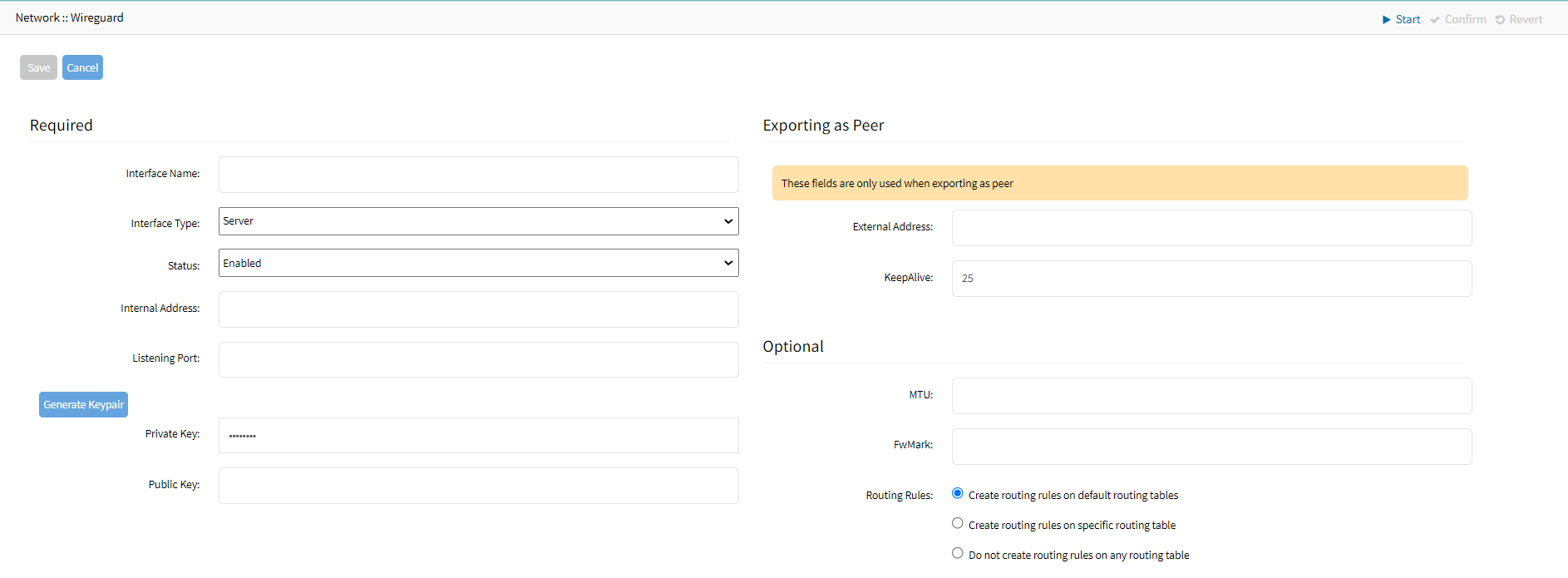
From the Status drop-down, select Enabled.
Enter an Internal Address (Example: 172.16.254.1/32); this IP Address is used as an internal interface IP Address. In most cases, you can use a /32 IP address.
Internal Address
The internal IP address assigned to the Wireguard interface is used for Cluster configuration and BPG and OSP peering configurations.
Enter a UDP Listening Port (Example: 9001), and the server will listen to this UDP for incoming client sessions. The UDP port must be opened on the firewall
Click Generate Keypair, to create a new Private/Public RSA key pair. This key pair is used to secure the connection
The Public key is exchanged with authorized Wireguard Clients.In the Exporting as Peersection:
Define the External Address (Example: 10.1.1.2) through which the server is reachable
Enter the KeepAlive value. The value is in seconds and provides a keep-alive functionality for the overlay network. The value should be between 10 - 120 sec, and the recommended value is 25 sec
You can leave the Optional settings on default
The Server configuration can be exported to a file for easy import into clients as a peer
Note
When you export a configuration, the hostname of the device is prefixed to the interface name. For example, Nodegrid_NG2.conf is the name of a sample exported conf file where Nodegrid is the hostname and NG2 is the name of the interface
Go to the Network :: VPN :: Wireguard page
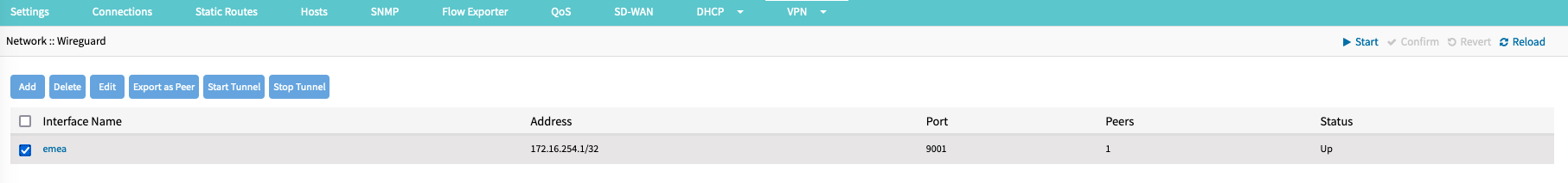
Select the Interface Name
Click Export Peer
The file is downloaded to the local download location
Client (Peer) Configuration
Wireguard's security is based on a mutually trusted RSA Keypair exchange, which requires exchanging public key information in both directions.
This means that every client must be specifically allowed and trusted on the server. This differs from most IPSec implementations, which are based on Pre-Shared key authentication, and the server might accept multiple connections with a valid preshared key without explicitly whitelisting clients. Wireguard does not support this method.
The exchange of public keys dramatically improves security, specifically on the client side. No Client has the required information to intercept or imitate other clients, and clients can be individually removed and disabled from the configuration without impacting any other client. This eliminates the requirement to rotate preshared keys regularly.
Clients can be created manually or by importing a Peer Export File, which can be made on the client.
Compleat Client-side configuration first
Due to the mutual exchange of Public Keys, it is recommended first to complete the Client-side configuration and then authorize the client on the server-side
Manual Peer Configuration
To allow a client/peer to connect to the server, create a peer using the following steps (for a full list of options, look here):
Go to the Network :: VPN drop-down :: Wireguard page
Click on the Server Interface (Example: emea) configuration that was created in the previous step
Click on Add (opens dialog)
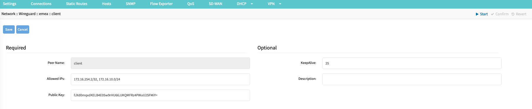
Enter a Peer Name (Example: client); this name is used to identify the client and must be a string without spaces or special characters
Provide a list of Allowed IP addresses or ranges (Example: 172.16.234.2/32, 172.16.10.0/24). This list is used in the default configuration to create the required routing information. For Host-to-Host communication, the list should contain only the internal IP address of the client. For site-to-site configurations, it should contain the remote IP network range
Provide the client Public Key, which was created during the client-side setup
It is recommended that a KeepAlive value is provided. The value is in seconds and provides a keep-alive functionality for the overlay network. The value should be between 10 - 120 sec, and the recommended value is 25 sec
KeepAlive and Handshake
Wireguard uses a " Handshakes " concept, similar to heartbeats. Handshakes are renewed every 2 minutes but are passive. This means handshakes are not proactively exchanged; for this, the KeepAlive feature is used. If no handshake is available or older than 2 minutes, this indicates a connection issue.
For this reason, it is recommended to always define a KeepAlive value.
Option: Provide a Description for the Client; this is a free text field that supports spaces and special characters
Import Peer from Client Export File
Go to the Network :: VPN drop-down :: Wireguard page
Click on the Server Interface (Example: emea) configuration that was created in the previous step
Click Import Peer (displays dialog)
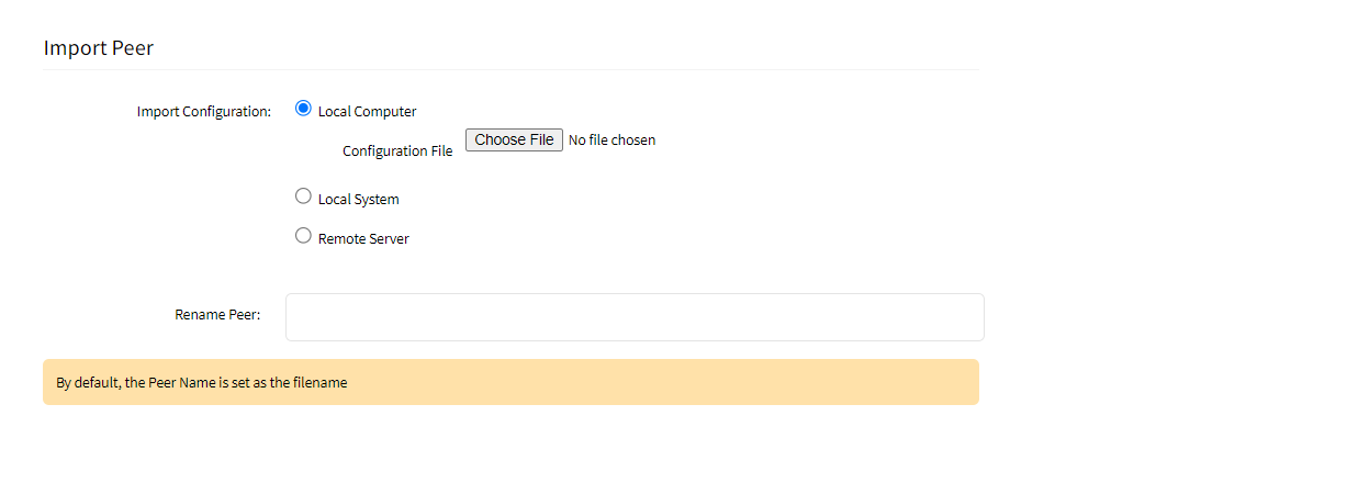
Provide the file location, which can be located locally (Local System) on the server, on a workstation (Local Computer), or on a Remote Server
In the Rename Peer field, enter a Peer Name (Example: client); this name is used to identify the client and must be a string without spaces or special characters. If you do not provide a Name the default name is taken from the imported file.
Click Save
After the Peer was imported, click on the newly created peer (Example: Client)
Update the Allowed IP (Example: 172.16.254.2/32, 172.16.10.0/24) configuration and include the client's network range
Validate the KeepAlive setting. The value is in seconds and provides a keep-alive functionality for the overlay network. The value should be between 10 - 120 sec, and the recommended value is 25 sec

Client-Side Configuration
The following configuration steps are required for each client to take part in the Wireguard VPN/Overlay network.
Client Interface Configuration
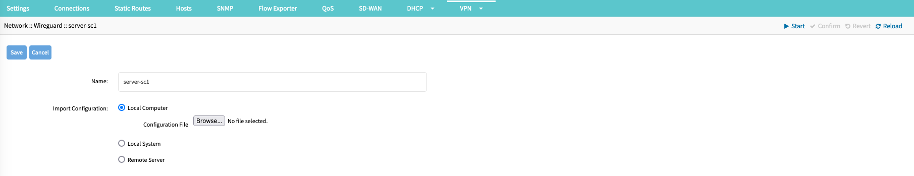
To configure a client interface, use the following steps (for a full list of options, look here):
Go to the Network :: VPN :: Wireguard page
Click Add
Enter an Interface Name (Example: server-sc1), this name is used for the network interface
On the Interface Type drop-down, select one Client
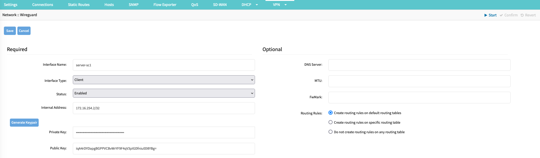
On the Status drop-down, select Enabled
Enter an Internal Address (Example: 172.16.254.2/32); this IP Address is used as an internal IP Address that is assigned to the interface
Internal Address
The internal IP address assigned to the Wireguard interface is used for Cluster configuration and BPG and OSP peering configurations.
Click on Generate Keypair, to create a new Private/Public RSA key pair. This key pair is used to secure the connection. The Public key is exchanged with the server
Leave other settings on default
The Client configuration can be exported to a file for easy import into the server as a peer
Go to the Network :: VPN :: Wireguard page
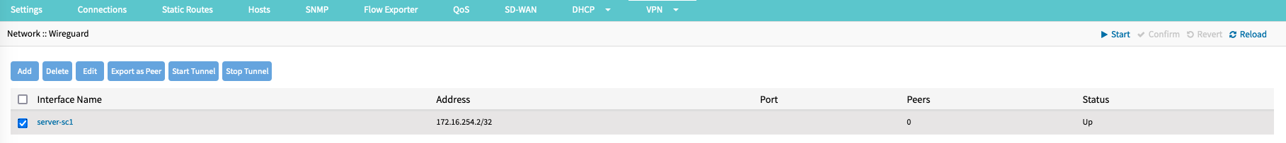
Select the Interface Name
Click Export Peer
The file is downloaded to the local download location
Server (Peer) Configuration
Wireguard's security is based on a mutually trusted RSA Keypair exchange, which requires exchanging public key information in both directions. This means that every client must be specifically allowed and trusted on the server.
Manual Server (Peer) Configuration
To allow a client/peer to connect to the server, create a peer using the following steps (for a full list of options, look here):
Go to the Network :: VPN drop-down:: Wireguard page
Click on the Client Interface (Example: server-sc1) configuration that was created in the previous step
Click on Add (opens dialog)
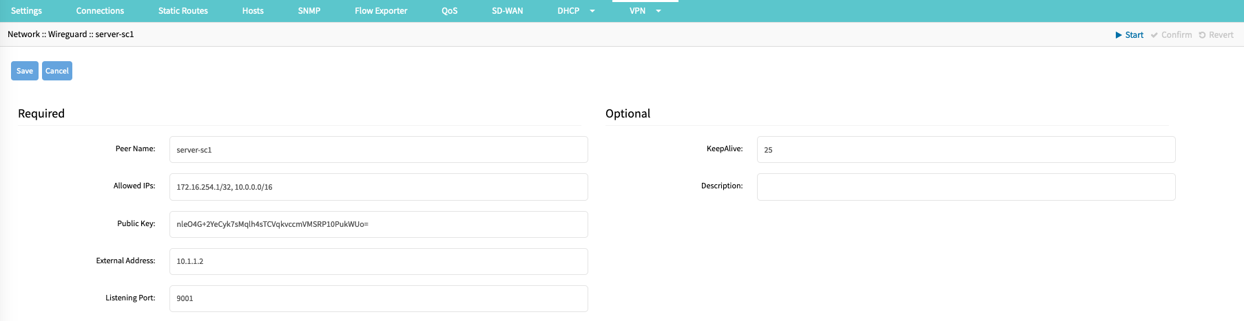
Enter a Peer Name (Example: server-sc1); this name is used to identify the server and must be a string without spaces or special characters
Provide a list of Allowed IP addresses or ranges (Example: 172.16.254.1/32,10.0.0.0/16). This list is used in the default configuration to create the required routing information. For Host-to-Host communication, the list should contain only the internal IP address of the server. For site-to-site configurations, it should contain the remote IP network range
Provide the client Public Key, which was created during the server-side setup
Provide the Public IP or FQDN of the server as an External Address (Example: 10.1.1.2)
Provide the UDP Listening Port (Example: 9001) on which the server is reachable.
It is recommended that a KeepAlive value of 25 is provided. The value is in seconds and provides a keep-alive functionality for the overlay network.
KeepAlive and Handshake
Wireguard uses a " Handshakes " concept, similar to heartbeats. Handshakes are renewed every 2 minutes but are passive. This means handshakes are not proactively exchanged; for this, the KeepAlive feature is used. If no handshake is available or older than 2 minutes, this indicates a connection issue.
For this reason, it is recommended always to define a KeepAlive value.
Option: Provide a Description for the Client; this is a free text field that supports spaces and special characters
Import Peer from Server Export File
Go to the Network :: VPN drop-down :: Wireguard page
Click on the Client Interface (Example: server-sc1) configuration that was created in the previous step
Click Import Peer (displays dialog)
Enter a Peer Name; this name is used to identify the client and must be a string without spaces or special characters
Provide the file location, which can be located locally (Local System) on the server, on a workstation (Local Computer), or a Remote Server.
Click Save.
After the Peer was imported, click on the newly created peer (Example: server-sc1)
Update the Allowed IP (Example: 172.16.254.1/32, 10.0.0.0/16) configuration and include the client's network range
Validate the KeepAlive setting. The value is in seconds and provides a keep-alive functionality for the overlay network. The value should be between 10 - 120 sec, and the recommended value is 25 sec
Appendix
Start Tunnel
Go to the Network :: VPN :: Wireguard page
On the table, select the interface.
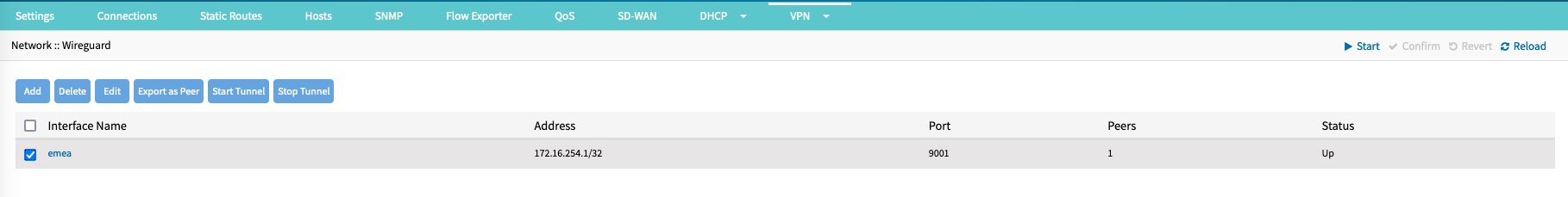
Click Start Tunnel (Post Up)
Stop Tunnel
Go to Network :: VPN :: Wireguard.
On the table, select the interface.

Click Stop Tunnel (Post Down).
Tunnel Status
Go to the Tracking :: Network :: Wireguard page
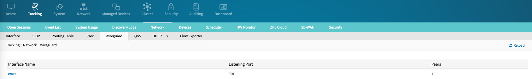
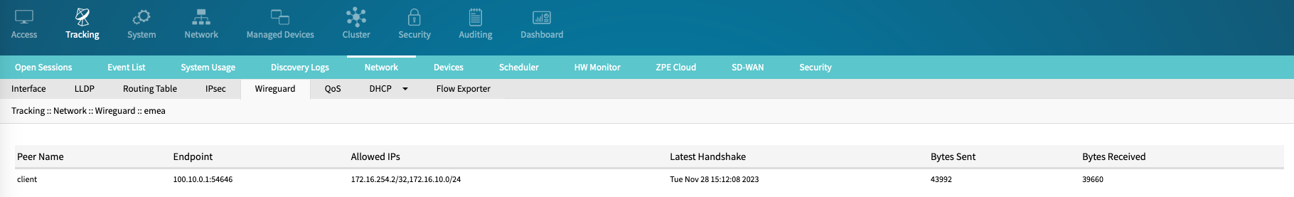
To review peer details and identify the overlay status, click on the interface name to drill down to the peer details.
The table will identify:The Peer Name
Current End Point (public IP address and port number) details. This information can dynamically change, depending on roaming information provided by the peer/client
The latest Handshake timestamp. If this is older than 2 minutes or blank, this indicates an issue with the connection; if it was recently updated, is the tunnel up and working
Bytes Sent
Bytes Received
Full List of Server Interface Options
Setting | Value | Comment |
|---|---|---|
Interface Name | network interface name | interface name must be string without spaces or special characters |
Interface Type | Options:
| |
Status | Options:
| |
Internal Address | <IP Address>/<Bit Mask> | IP Address (IPv4 or IPv6) that is assigned to the network interface |
Listening Port | UDP port on which the server is listening for incoming connections | Only required for Server configuration |
Private Key | Private Key | Users can either auto-generate a Private/Public keypair, by using the "Generate Keypair" option (recommended), |
Public Key | Public Key | Users can either auto-generate a Private/Public keypair, by using the "Generate Keypair" option (recommended), |
External Address | Optional: Public IP address | This setting is only used for Client configuration exports. It is used to simplify the Client Configuration |
MTU | <MTU size> | |
FwMark | <FwMark> | This is an advanced option that allows tagging of all traffic in the kernel with a specified FwMark. This can be used for advanced firewall or traffic steering options. |
Routing Rules | Options:
|
Full List of Peer Options
Settings | Value | Comment |
|---|---|---|
Peer Name | <Peer Name> | The wireguard name used to identify the peer must be a string without spaces or special characters |
Allowed IPs | <List of IP's and IP Ranges> | Comma-separated list of IP addresses or IP networks, which are allowed to arrive from this peer or to be sent to the peer. In the default configuration, based on this list are the appropriate routing entries created |
Public Key | <Public Key> | Public key from the client/peer |
KeepAlive | keep alive interval in seconds (recommended value 25) | |
description | description | Description |
External Address | <IP or FQDN> | Only Available on Client connections |
Listening Port | <PORT> | Only Available on Client connections |
CLI Commands
Add the Wireguard interface configuration details, and apply these commands:
[admin@nodegrid /]# cd /settings/wireguard/
[admin@nodegrid {wireguard}]# set
   interface_name=
   listening_port=
   public_key=
   external_address=
   interface_type=
   mtu=
   routing_rules=
   fwmark=
   internal_address=
   private_key=
   status=
[admin@nodegrid {wireguard}]# commit
Configure peers/clients:
[admin@nodegrid wireguard]# cd Interface_Name/
[admin@nodegrid Server_Interface]# cd peers/
[admin@nodegrid peers]# add
[admin@nodegrid {peers}]# set
   allowed_ips=
   keepalive=
   peer_name=
   external_address=
   listening_port=
   public_key=
[admin@nodegrid {peers}]# commit
Failover
Wireguard natively supports roaming; this means a client can dynamically update its end-point information and inform the server about the updated details. This allows Nodegrid Clients to be connected to carrier-grade NAT connections and a wide range of other standard WAN connections. The Wireguard tunnel will also automatically follow the Nodegrid's Failover configuration without any additional configuration.
Challenges arise in situations where both end-point details change at the same time. This can happen in examples where, under normal circumstances, the overlay network uses the internal LAN to connect to the server but must switch to the server's public end-point address in case the LAN network has an outage or the server is not reachable for other reasons over the LAN.
The following script allows Nodeghrid to update the Endpoint Addresses dynamically in these situations. The example script provides an example script for a single tunnel, but can easily expanded for multiple tunnels by duplicating the Tunnel section.
Installation of Failover script file
Wireguard Tunnel Must Exist
It is assumed that the Wireguard tunnel was already configured and is working.
Network Failover Events 144 and 145
The script specifically uses Nodegrid Events 144 and 145, triggered in case of a Network Failover. The script can also be used with other Events, but the appropriate checks must be adopted. in the script
Open a console connection with the admin user
Enter into the root shell.
shell sudo su -Lookup the required details with wg show:
interface: server-sc1
  public key: iqA4rDYDapgBGPPVCBvWrYF9F4qV3pIGDfniu0D8YBg=
  private key: (hidden)
  listening port: 54646

peer: nleO4G+2YeCyk7sMqlh4sTCVqkvccmVMSRP10PukWUo=
  endpoint: 203.0.13.1:9001
  allowed ips: 172.16.254.1/32, 10.0.0.0/16
  latest handshake: 4 seconds ago
  transfer: 780 B received, 1.23 KiB sent
  persistent keepalive: every 25 seconds
Navigate to:
cd /etc/scripts/auditingcreate the script file wireguard-failover.sh.
vi wireguard-failover.shcopy the content into the file and adjust the following parameters:
tunnel_interface_1_name = Tunnel Interface Name as provided in the WebUI
tunnel_interface_1_peer = Peer Identifier, this is equal to the public key of the peer
tunnel_interface_1_endpoint = Normal Endpoint IP address and port in the format of <IP Address>:<PORT Number>, i.e. 10.10.1.1:9001
tunnel_interface_1_backup = Backup Endpoint IP address and port in the format of <IP Address>:<PORT Number>, i.e. 100.0.0.1:9001
#!/bin/bash

# This script is meant to dynamically change a wireguard endpoint
# Whenever an event ocurrs, it will execute this script passing the Event
# number as the first argument plus all the arguments that this events
# pass to SNMP TRAP. See Nodegrid-TRAP-MIB.mib to see all args for each event.

EVENT_NUMBER="$1" #argument 1 is always the event number
LOG_FILE=/var/log/messages
DELAY=1

###### Tunnel 1 #######
# Dplicate the whole section for any additional Tunnel
tunnel_interface_1_name=<Interface Name>
tunnel_interface_1_peer=<Peer Name>
tunnel_interface_1_endpoint=<Interface Primary Endpoint ip:port>
tunnel_interface_1_backup=<Interface Backup Endpoint ip:port>

if [ ${EVENT_NUMBER} -eq 144 ]; then
  sleep ${DELAY}
  wg set ${tunnel_interface_1_name} peer ${tunnel_interface_1_peer}  endpoint ${tunnel_interface_1_backup}
  echo "Changed Wireguard Tunnel ${tunnel_interface_1_name} peer ${tunnel_interface_1_peer}  to endpoint ${tunnel_interface_1_backup}" >> ${LOG_FILE}
fi

if [ ${EVENT_NUMBER} -eq 145 ]; then
  sleep ${DELAY}
  wg set ${tunnel_interface_1_name} peer ${tunnel_interface_1_peer} endpoint ${tunnel_interface_1_endpoint}
  echo "Changed Wireguard Tunnel ${tunnel_interface_1_name} peer ${tunnel_interface_1_peer}  to endpoint ${tunnel_interface_1_endpoint}" >> ${LOG_FILE}
fi
### END Tunnel 1 ####
Example:
#!/bin/bash

# This script is meant to dynamically change a wireguard endpoint
# Whenever an event ocurrs, it will execute this script passing the Event
# number as the first argument plus all the arguments that this events
# pass to SNMP TRAP. See Nodegrid-TRAP-MIB.mib to see all args for each event.

EVENT_NUMBER="$1" #argument 1 is always the event number
LOG_FILE=/var/log/messages
DELAY=1

tunnel_interface_1_name=server-sc1
tunnel_interface_1_peer=nleO4G+2YeCyk7sMqlh4sTCVqkvccmVMSRP10PukWUo=
tunnel_interface_1_endpoint=10.1.1.2:9001
tunnel_interface_1_backup=203.0.13.1:9001

if [ ${EVENT_NUMBER} -eq 144 ]; then
  sleep ${DELAY}
  wg set ${tunnel_interface_1_name} peer ${tunnel_interface_1_peer}  endpoint ${tunnel_interface_1_backup}
  echo "Changed Wireguard Tunnel ${tunnel_interface_1_name} peer ${tunnel_interface_1_peer}  to endpoint ${tunnel_interface_1_backup}" >> ${LOG_FILE}
fi

if [ ${EVENT_NUMBER} -eq 145 ]; then
  sleep ${DELAY}
  wg set ${tunnel_interface_1_name} peer ${tunnel_interface_1_peer} endpoint ${tunnel_interface_1_endpoint}
  echo "Changed Wireguard Tunnel ${tunnel_interface_1_name} peer ${tunnel_interface_1_peer}  to endpoint ${tunnel_interface_1_endpoint}" >> ${LOG_FILE}
fi
save the file with
:wq.make the file executable.Example:
chmod +x /etc/scripts/auditing/wireguard-failover.sh
Assign script file to Events 144 and 145
Open a WebUI and Navigate to the Auditing :: Events :: Event List page
Navigate to Event 144
Click the Event ID
Assign the script to the Event ID
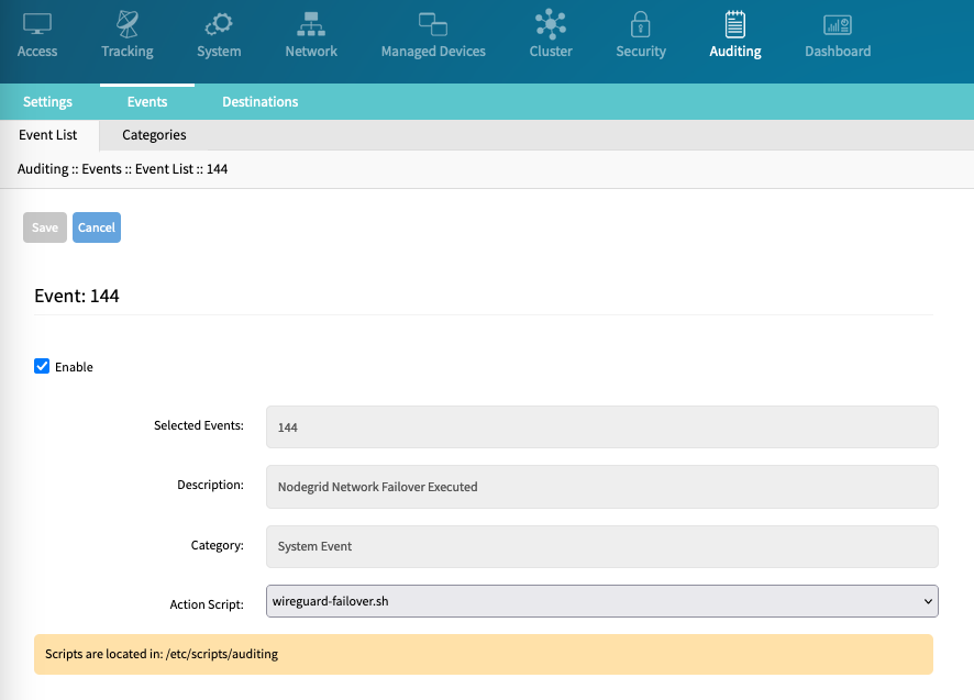
Repeat with Event 145.