Rack Power Distribution Units (Rack PDUs) are essential components of data center infrastructure, yet it's still common to configure them manually via command-line interfaces. This approach is inefficient, especially at scale, and presents three key challenges:
Skilled engineers must be on-site to perform configuration tasks.
Rack PDUs must be configured individually, which consumes valuable time.
Manual configuration increases the risk of inconsistencies and human error, potentially leading to costly failures or compliance issues.
To address these challenges, the Nodegrid platform integrates seamlessly with Server Technology PDUs' Zero Touch Provisioning (ZTP) capabilities. By combining ZTP with out-of-band remote access, the Nodegrid platform allows teams to automate deployment and centralize the management of Rack PDUs. This solution provides three main benefits:
Out-of-band access enables engineers to configure and troubleshoot remotely via a web browser.
Zero-touch provisioning automatically configures all Rack PDUs at boot-up, saving hours of manual work.
Automating configuration and firmware updates eliminates human intervention, reducing the risk of failures and non-compliance.
This guide outlines the required steps to configure a Nodegrid appliance to act as a Zero Touch Provisioning Server for Server Technology PDUs and guides users through the first deployment and management of a Server Technology Rack PDU.
Model Dependencies
Server Technology Rack PDUs support two versions of the ZTP process, which is dependent on the used controller. This guide will provide the required steps for both controller versions and will highlight the required differences as needed.
1 Requirement
1.1 ZPE Systems
Nodegrid appliance guide uses a Bold SR as an example with
Minimum one LAN port to which the Rack PDUs are connected
Minimum one USB or RJ45 Console port depending on Rack PDU model for console access
Minimum in one free Nodegrid Managed Devices Licenses, one license per Rack PDU
Managed Devices Licenses
Depending on the Nodegrid model used, the required licenses are included with the model.
1.2 Server Technology
Minimum 1 x Rack PDU from the Server Technology PRO1/2, PRO3X or PRO4X series
1.3 Accessories
Network Switch (Optional), appliances of the Nodegrid SR family provide integrated network ports, which can be used to directly connect Rack PDUs to the Nodegrid appliance
Cat5/Cat6 cables for network connectivity
PRO1/2 - Cat5/Cat6 patch cable for console access
PRO3X/4X - USB-B to USB-A cable for console access
2 Technical Overview
This guide utilizes a Nodegrid Bold SR. The appliance will act as a DHCP and ZTP server for a directly connected Rack PDU. The appliance will host the required configuration and firmware files for the ZTP process.
As part of the deployment, the Rack PDU will automatically be added to the Nodegrid management interface. This enables enable users to easily perform power control actions, such as Power-Off, Power-On or Power-Cycle, access the console interface and the WebUI of the Rack PDU, without directly exposing the Rack network interface to the management network, providing isolation to the connected Rack PDUs.
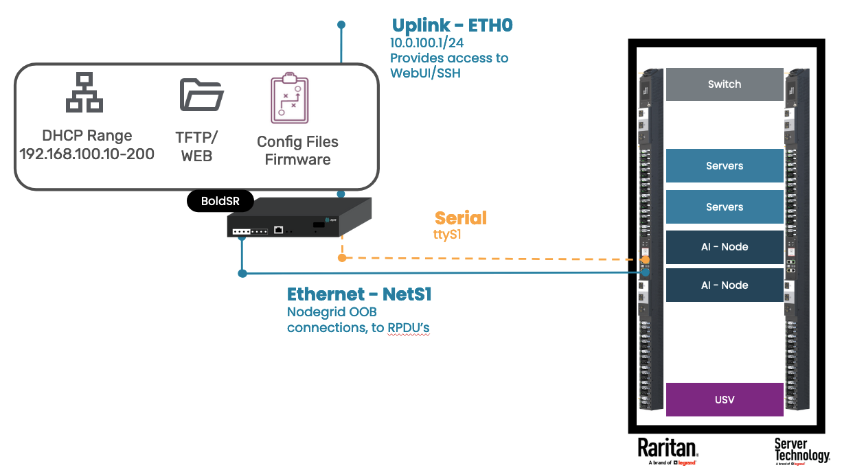
Appliance | Setting Type | Setting | Value | Comment |
|---|---|---|---|---|
Bold SR | Network Settings | ETH0 | DHCP or Static | Instructions on how to get started with a Bold SR see here |
BACKPLANE0 | 192.168.100.1/24 | BACKPLANE0 interface provides connectivity to NestS1-4 via an integrated switch | ||
DHCP Server | Scope | 192.168.100.0 - 255.255.255.0 | ||
Range | 192.168.100.10-192.168.100.200 | |||
File Storage | HTTP | datastore | Required for PRO3X and PRO4X | |
TFTP | datastore | Required for PRO1 and PRO2 | ||
Managed Devices | ttyS1 | Enabled, 9600 baud | will provide console access top Rack PDU | |
Rack PDU | Config Files | ZTP Configuration File - PRO1/PRO2 |
| For PRO1 and PRO2 |
| For PRO3X and PRO4X | |||
Firmware file | firmware.bin |
3 Preparation
The following section outlines the preparation work, which includes preparing the DHCP server, file server, and Nodegrid auto-discovery. These steps are typically only required once to set up the environment and apply to all Server Technology Rack PDU models.
3 Manual Configuration
3.1 DHCP Server Configuration
The ZTP process of the Server Technology PDUs depends on Vendor-specific attributes and configurations which need to be manually added to the DHCP server configuration. These settings are Model specific, the guide will highlight the sections that must be adjusted depending on the used model.
Editing of Configuration Files
Manual editing of configuration files can lead to configuration mistakes. We recommend that each configuration file is backed up before editing. To edit files, the user can use the vi editor, see the cheat sheet here on how to use vi.
To add the required configuration follow these steps:
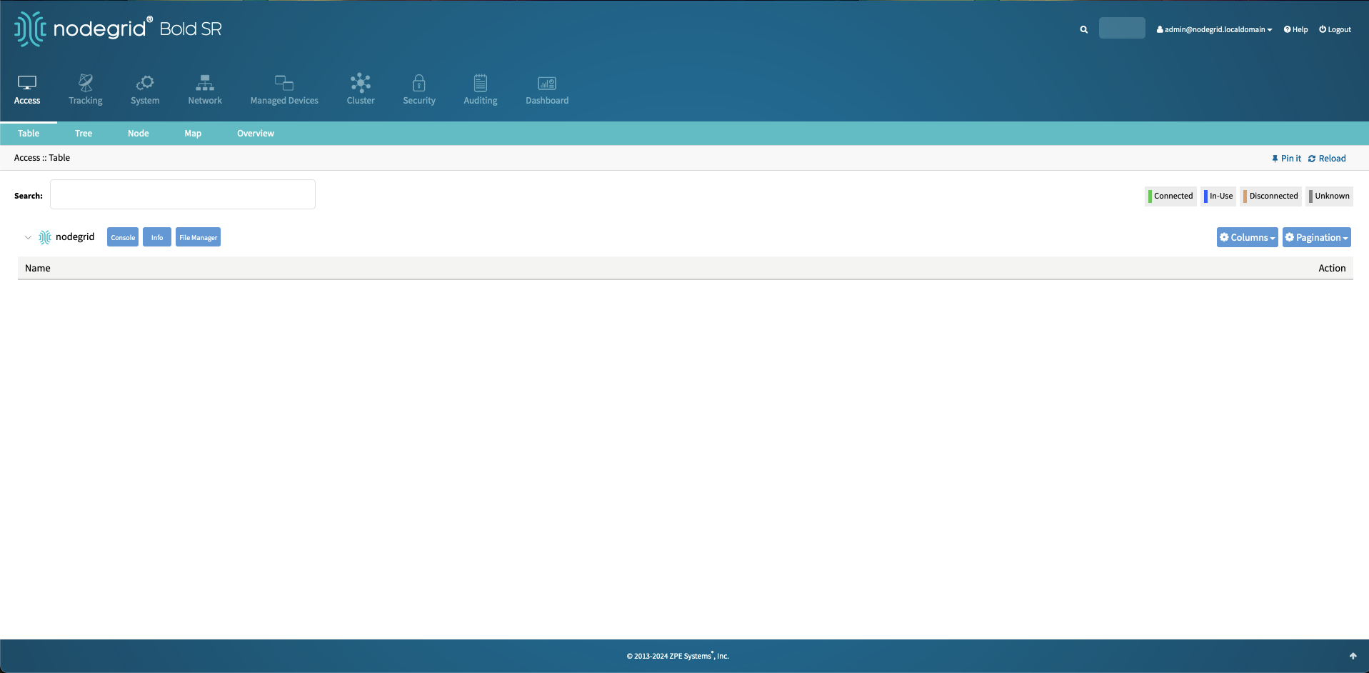
In the WebUI navigate to Access and click on Console. This opens a new Window with the Console interface displayed.
Enter the root shell.
shell sudo su -Create a backup of the DHCP configuration file.
cp /etc/dhcp/dhcpd.conf /etc/dhcp/dhcpd.conf.bckEdit the DHCP configuration file.
vi /etc/dhcp/dhcpd.confNavigate to the section that contains the vendor-specific details for the Nodegrid appliances and add the following section.
option space servertech hash size 3;
option servertech.identifier code 1 = text;
option servertech.ztp-url code 2 = text;

set vendor-string = option vendor-class-identifier;
option space RARITAN code width 1 length width 1 hash size 3;
option RARITAN.pdu-tftp-server code 1 = ip-address;
option RARITAN.pdu-update-control-file code 2 = text;
option RARITAN.pdu-update-magic code 3 = text;
option RARITAN.pdu-model code 4 = text;
option RARITAN.pdu-serial code 5 = text;
option RARITAN.pdu-cascading-info code 6 = text;
option RARITAN.pdu-http-uri-base code 7 = text;
option local-encapsulation code 43 = encapsulate RARITAN;
Underneath the vendor-specific scope add a vendor-specific class. This class uniquely identifies each RACK PDU and ensures that the correct PDUs receive the correct configuration files. This also enables users to define unit-specific configurations, which are based on a unit's MAC address.
Configuration details
The following examples, require adjustments in cases where the Nodegrid IP address and the config file names deviate from the example.
Single Configuration File
class "servertech-ztp" {
match if substring (option vendor-class-identifier, 0, 10) = "ServerTech";
vendor-option-space servertech;
option servertech.identifier "STI Params";
option servertech.ztp-url "tftp://192.168.100.1/datastore/config-servertech.ini";
}
class "raritan" {
match if option vendor-class-identifier = "Raritan PDU 1.0";
vendor-option-space RARITAN;
option RARITAN.pdu-tftp-server 192.168.100.1;
option RARITAN.pdu-update-control-file "fwupdate.cfg";
option RARITAN.pdu-update-magic "20240910-0001";
option vendor-class-identifier "Raritan PDU 1.0";
}
Configuration File based on MAC Address
class "servertech-ztp" {
match if substring (option vendor-class-identifier, 0, 10) = "ServerTech";
vendor-option-space servertech;
option servertech.identifier "STI Params";
option servertech.ztp-url "tftp://192.168.100.1/datastore/config-servertech-${mac}.ini";
}
class "raritan" {
match if option vendor-class-identifier = "Raritan PDU 1.0";
vendor-option-space RARITAN;
option RARITAN.pdu-tftp-server 192.168.100.1;
option RARITAN.pdu-update-control-file "fwupdate.cfg";
option RARITAN.pdu-update-magic "20240910-0001";
option
Save the changes.
Full Example
see Example dhcp.conf file for a full example
Before restarting the service validate the config file.
dhcpd -t -cf /etc/dhcp/dhcpd.confOutput
root@nodegrid:~# dhcpd -t -cf /etc/dhcp/dhcpd.conf
Internet Systems Consortium DHCP Server 4.4.3
Copyright 2004-2022 Internet Systems Consortium.
All rights reserved.
For info, please visit https://www.isc.org/software/dhcp/
Config file: /etc/dhcp/dhcpd.conf
Database file: /var/lib/dhcp/dhcpd.leases
PID file: /var/run/dhcpd.pid
Restart the DHCP server with the command.
/etc/init.d/dhcp-server restart
3.2 Configure File Server - TFTP and Web
3.2.1 Configure TFTP Server
From the root shell edit perform the following steps
Create a backup of
/etc/xinetd.d/tftpdfile.cp /etc/xinetd.d/tftpd /etc/xinetd.d/tftpd.bckEdit
/etc/xinetd.d/tftpdfile.vi /etc/xinetd.d/tftpdChange the state of disabled to "no".
service tftp
{
        disable         = no
        socket_type     = dgram
        protocol        = udp
        flags           = IPv6
        wait            = yes
        user            = root
        group           = root
        server          = /usr/sbin/in.tftpd
        server_args     = -s /var/opt/tftpboot
}
Save the file.
Start the TFTP server.
/etc/init.d/xinetd startCreate a symlink to the datastore directory.
ln -s /var/local/file_manager/datastore /var/opt/tftpboot/Close the root shell, by using the
exitcommand or closing the session.
3.2.2 Configure HTTP file server
In the WebUI navigate to Security :: Services.
In the Web Service section, enable the option:
Enable HTTP/S File Repository.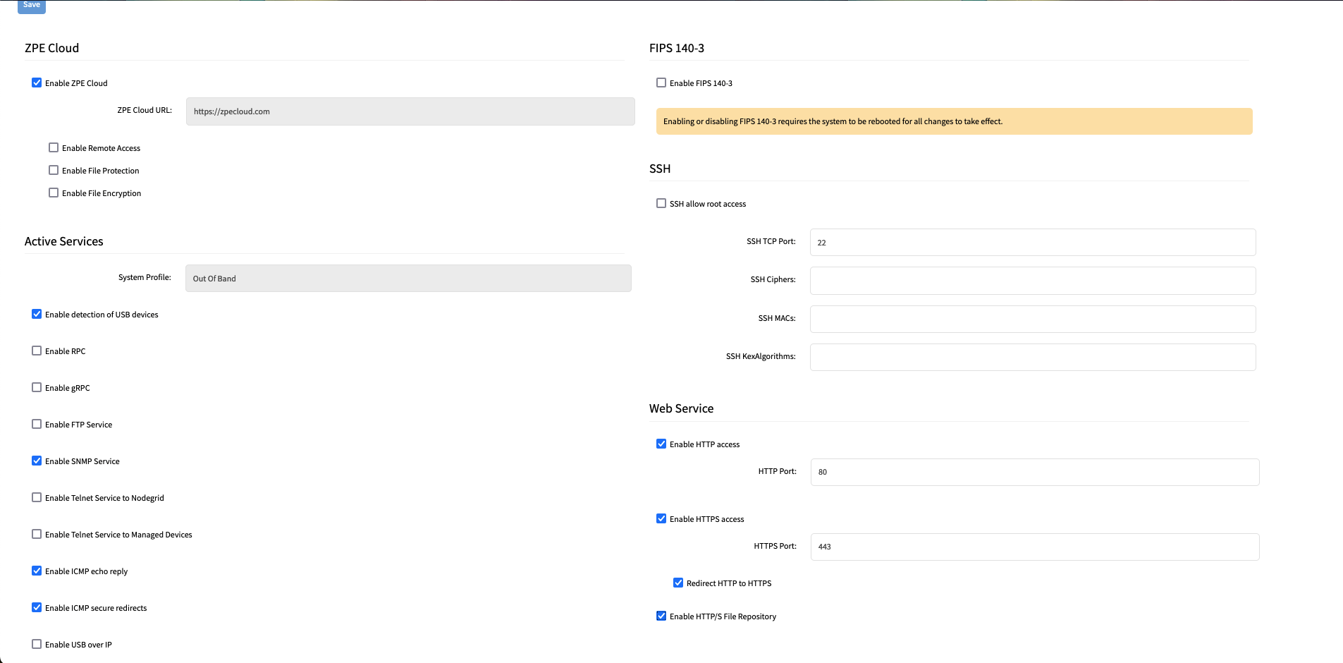
Click Save.
3.3 DHCP Scope Configuration
This section outlines how a new DHCP scope is configured on the Nodegrid appliance, which will be used for the ZTP process. For more details on DHCP configurations see here.
Navigate to Network :: Connections.
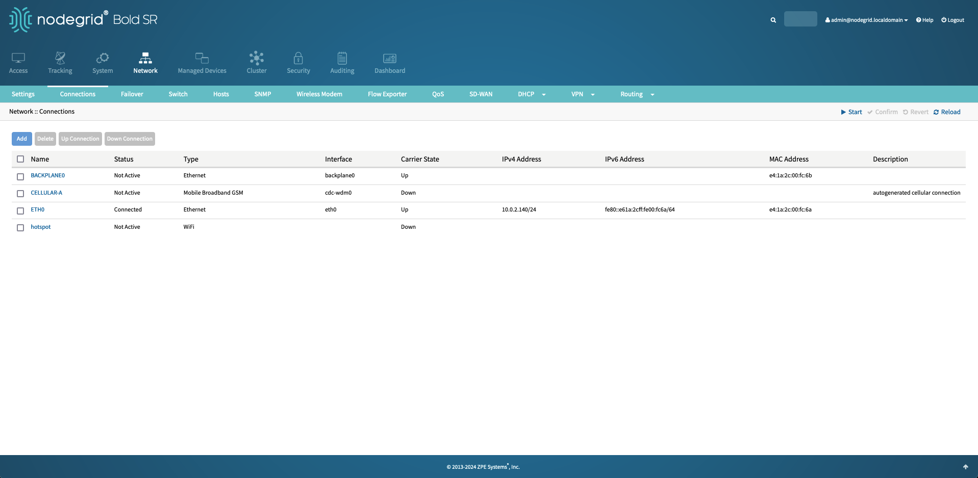
Select the BACKPLANE0 interface and assign a static IP address of 192.168.100.1 with a Bitmask of 24.
BACKPLANE0 will be used to interact with the Rack PDU's and the DHCP server will only listen on this interface.
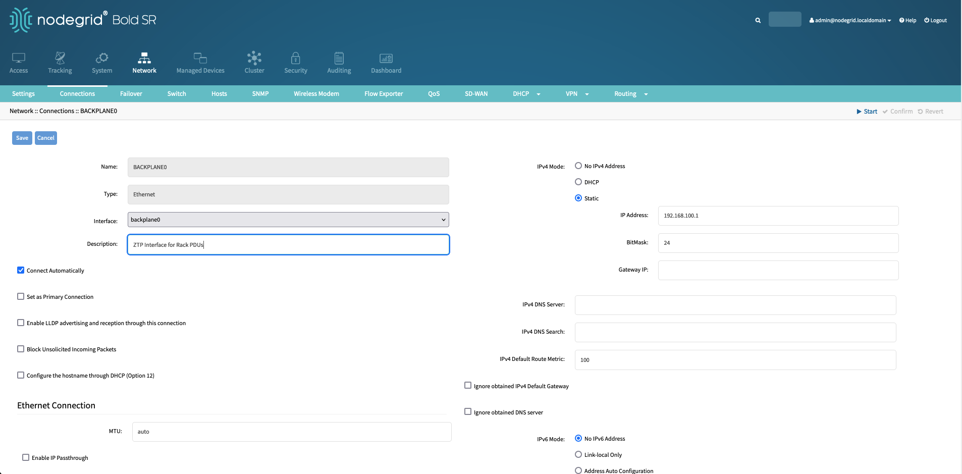
Save the changes.
Navigate to Network :: DHCP :: DHCP Server.
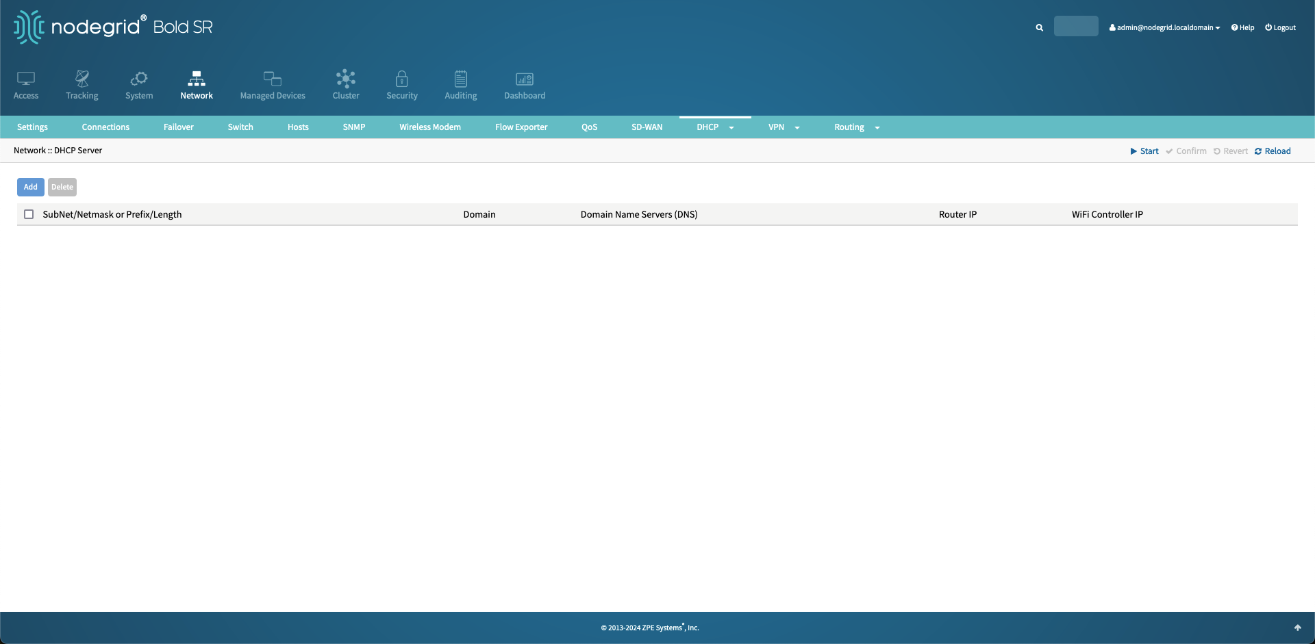
Click on Add to create a new DHCP scope and define the subnet as
192.168.100.0and Netmask as255.255.255.0.Additional Values
Define additional values as desired, but they are not required
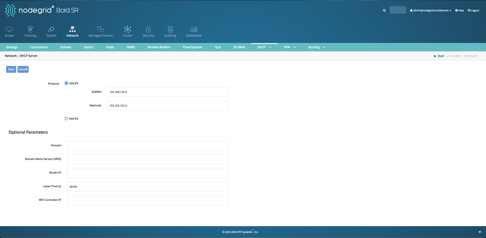
Save the configuration, this will create a new blank DHCP range.
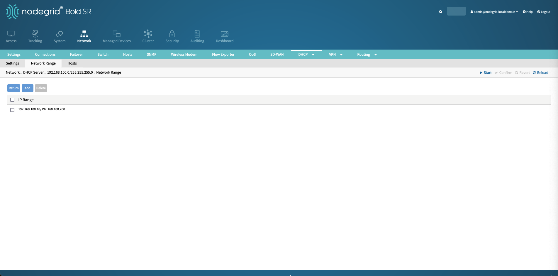
Click on the newly created DHCP range, navigate to Network Range and click Add.
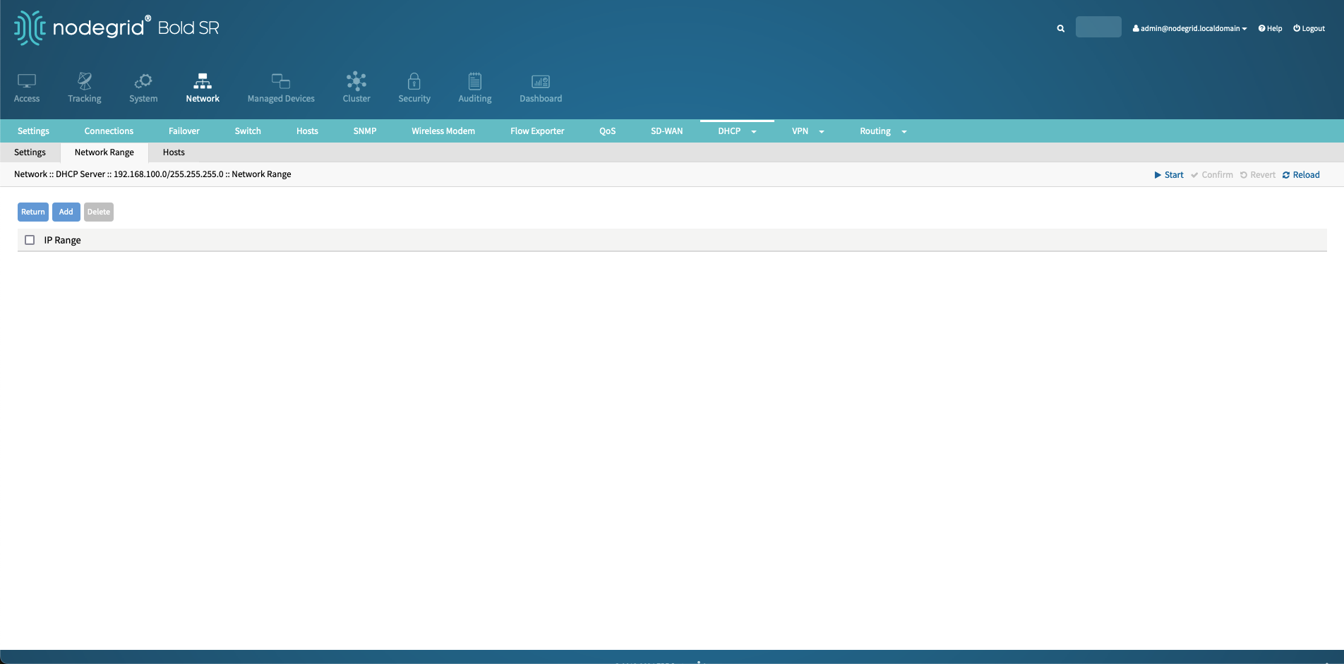
Define the network range by defining a start address (
192.168.100.10) and an end address (192.168.100.200).
Host Reservations
The DHCP server supports as well IP address reservations in the Hosts section of the DHCP scope section see here for more details
3.4 Nodegrid Managed Device Auto-Discovery
Optional
This step is optional and not required for the Zero Touch Provisioning process. This section enables the automatic discovery of provisioned Rack PDUs, so that the Rack PDUs can be managed through the Nodegrid appliance for ongoing maintenance and outlet control
The following section outlines the required steps that will automatically add the provisioned Rack PDUS to the Nodegrid management interface. As soon as a Rack PDU is discovered, the user can utilize the Nodegrid interface, to access the Rack PDU, via the WebUI, SSH, and Console, allowing users to easily control power outlets and monitor the power consumption.
Model Dependency
Availability of functionality will depend on the Rack PDU model used. Example: The functionality of power outlet control depends on the availability of the feature on the Rack PDU in use.
Nodegrid appliances can be configured through multiple interfaces, like the WebUI and the import_settings cli command. The import_settings command makes it easy to apply golden templates to Nodegrid appliances and configure the devices as needed. The following section documents both configuration methods allowing users to choose their preferred method/
3.4.1 Create a Rack PDU Device Template
The Auto Discovery process will create managed devices based on user-defined device templates.
3.4.1.1 Import_Settings
Start a Nodegrid Console connection to the appliance cli, the WebUI navigate to the Access screen and click on the console button.
Use the following command to start the import_settings process.
import_settingsUse the following import_settings commands to create the template device, by pasting the text into the CLI.
IMPORTANT
Adjust the password setting to the required value for the PDU.
/settings/devices/_template_servertech/access name=_template_servertech
/settings/devices/_template_servertech/access type=pdu_servertech
/settings/devices/_template_servertech/access web_url=http://%IP
/settings/devices/_template_servertech/access launch_url_via_html5=yes
/settings/devices/_template_servertech/access method=internal_browser
/settings/devices/_template_servertech/access username=admin
/settings/devices/_template_servertech/access credential=set_now
/settings/devices/_template_servertech/access password=MYPASSWORD
/settings/devices/_template_servertech/access allow_pre-shared_ssh_key=no
/settings/devices/_template_servertech/access enable_device_state_detection_based_on_network_traffic=yes
/settings/devices/_template_servertech/access enable_hostname_detection=no
/settings/devices/_template_servertech/access multisession=yes
/settings/devices/_template_servertech/access read-write_multisession=no
/settings/devices/_template_servertech/access enable_send_break=no
/settings/devices/_template_servertech/access icon=servertech.png
/settings/devices/_template_servertech/access mode=disabled
/settings/devices/_template_servertech/access expiration=never
/settings/devices/_template_servertech/access end_point=appliance
/settings/devices/_template_servertech/management ssh_and_telnet=yes
/settings/devices/_template_servertech/management credential=use_same_as_access
/settings/devices/_template_servertech/management snmp=yes
/settings/devices/_template_servertech/management snmp_version=v2
/settings/devices/_template_servertech/management snmp_community=private
/settings/devices/_template_servertech/logging data_logging=yes
/settings/devices/_template_servertech/commands/outlet command=outlet
/settings/devices/_template_servertech/commands/outlet enabled=yes
/settings/devices/_template_servertech/commands/outlet protocol=snmp
Press CTRL+D to start the import process. the command will indicate the success of the import.
Example:
[admin@nodegrid /]# import_settings
Type or paste data output from export_settings. Press <CTRL-D> to finish.
/settings/devices/_template_servertech/access name=_template_servertech
/settings/devices/_template_servertech/access type=pdu_servertech
.....
/settings/devices/_template_servertech/commands/outlet enabled=yes
/settings/devices/_template_servertech/commands/outlet protocol=snmp

Path: /settings/devices/_template_servertech/access Result: succeeded
Path: /settings/devices/_template_servertech/management Result: succeeded
Path: /settings/devices/_template_servertech/logging Result: succeeded
Path: /settings/devices/_template_servertech/commands/outlet Result: succeeded
Processed paths: 4 Rejected paths: 0
4.4.1.2 WebUI
To create a new device template follow these steps.
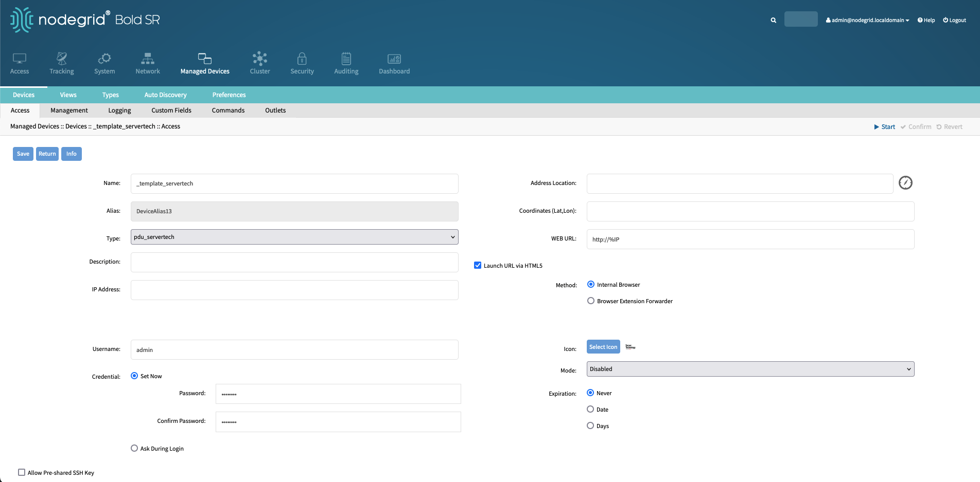
Navigate to Managed Devices.
Click on Add and create a new device with the following details:
Setting
Value
Comment
Name
_template_servertech
Type
pdu_servertech
IP Address
127.0.0.1
Username
admin
Password
!PASSWORD!
Mode
disabled
Enable device state detection based on network traffic (icmp)
Enabled
Icon
Server Technology
Save the template, this will create a new device
Click on the newly created device and finalize the configuration.
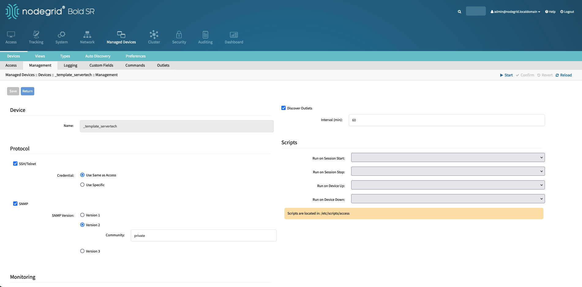
Navigate to the Devices Management section and configure the following settings:
Setting
Value
Comment
SNMP
Enable
SNMP Version:
Version 2
Community
private
Use the SNMP Community which is configured on the Rack PDU
Navigate to the Devices Commands section, click on Logging and enable Data Logging.
Setting
Value
Comment
Data Logging
Enabled
This feature enables data logging for all ssh sessions to the rack PDU
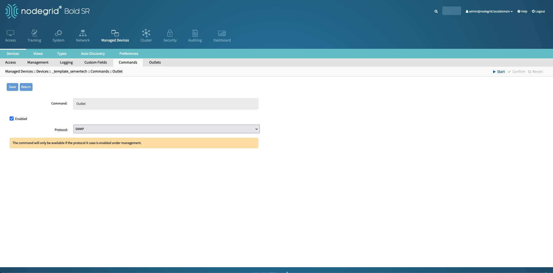
Navigate to the Devices Commands section, click on Outlet and change the Protocol to SNMP.
Setting | Value | Comment |
|---|---|---|
Protocol | SNMP | This protocol will be used to detect outlets and to enable power control functionality. |
3.4.2 Create Auto Discovery Rule
3.4.2.1 Import_Settings
Start a Nodegrid Console connection to the appliance cli, the WebUI navigate to the Access screen and click on the console button.
Use the following command to start the import_settings process.
import_settingsUse the following import_settings commands to create the template device, by pasting the text into the CLI.
/settings/auto_discovery/discovery_rules/_discover_servertech rule_name=_discover_servertech
/settings/auto_discovery/discovery_rules/_discover_servertech status=enabled
/settings/auto_discovery/discovery_rules/_discover_servertech method=dhcp
/settings/auto_discovery/discovery_rules/_discover_servertech action=clone_mode_on-demand
/settings/auto_discovery/discovery_rules/_discover_servertech clone_from=_template_servertech
/settings/auto_discovery/discovery_rules/_discover_servertech enforce_device_type=yes
/settings/auto_discovery/discovery_rules/_discover_servertech inherit_appliance_credentials=no
Press CTRL+D to start the import process. the command will indicate the success of the import.
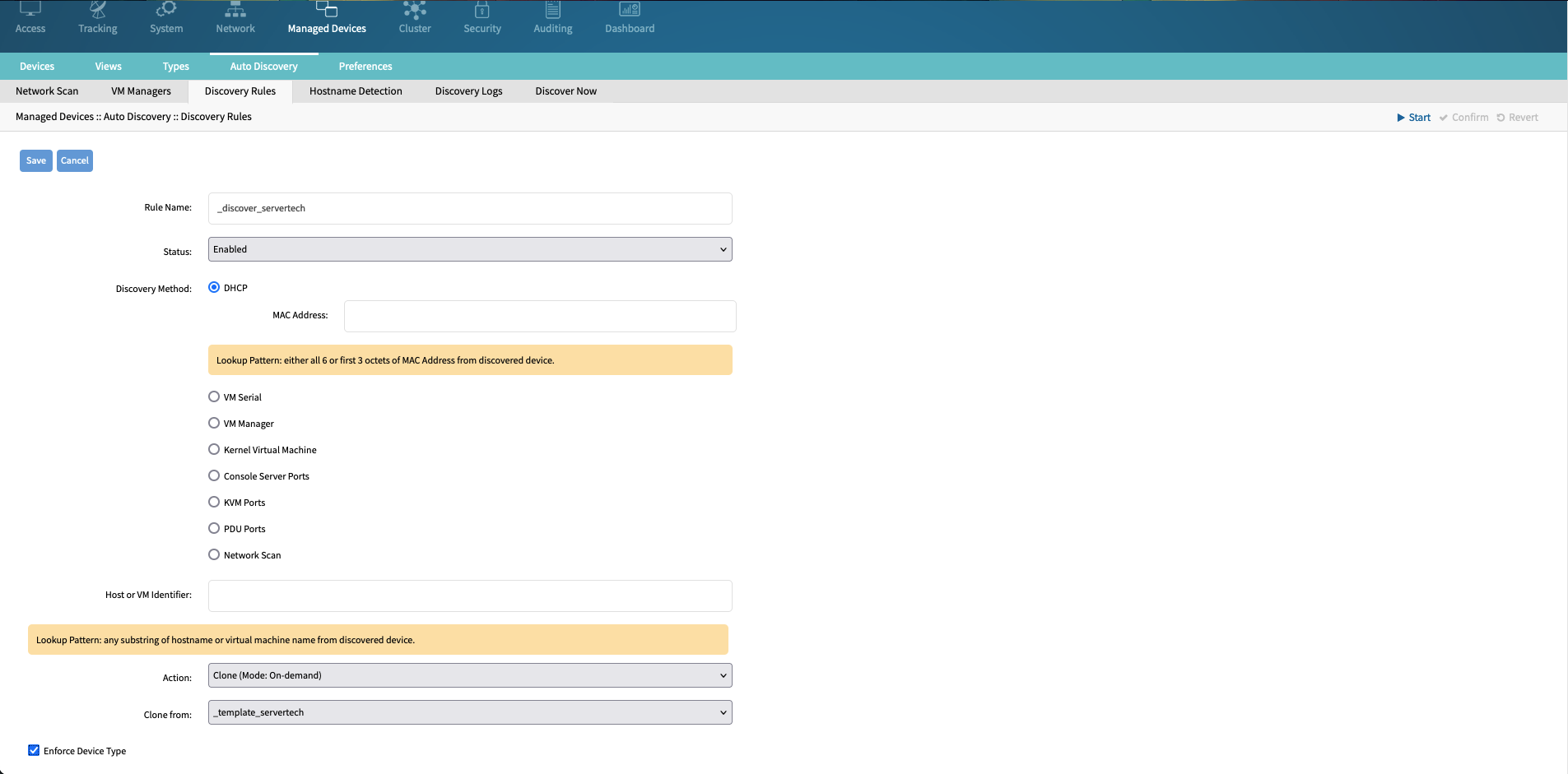
3.4.2.2 WebUI
Navigate to Managed Devices :: Auto Discovery :: Discovery Rules.
Click Add and create a new rule with the following settings.
Setting | Value | Comment |
|---|---|---|
Rule Name | _discover_servertech | |
Status | Enabled | |
Discovery Method | DHCP | |
Action | Clone (Mode: On-Demand) | |
Clone From | _template_servertech | |
Enforce Device Type | Enabled |
4 ZTP Configuration Files Configuration
4.1 Preparing ZTP Configuration Files
Depending on the Rack PDU models used different configuration files are required. The following section will provide an overview and example configuration files for the Server Technology PRO1/2 and the PRO3X and PRO4X series. See the official documentation for more details:
For Server Technology PRO1/2 see here for reference documentation and a template file.
For Server Technology PRO3X and PRO4X based on Xerus controller platform, see here.
4.1.1 Server Technology PRO1/2 models - Server Technology INI Configuration
Download the official STIC template file
Create a new text file, based on the downloaded template. with the name
config-servertech.iniorconfig-servertech-${mac}.ini, where by${mac}represents the Rack PDUs MAC address.Adjust values as needed and required. Ensure that username, password and SNMP settings which are configured match the created device template in step [[#3.4.1 Create a Rack PDU Device Template]]
Example:
[snmp]
get community: public
set community: private
v2: enabled

[user]
username: admn
password: MYPASSWORD
Firmware Update
Server Technology PRO1 and PRO 2 Rack PDUs Zero Touch Provisioning process does not support firmware updates.
4.1.2 Server Technology PRO3X and PRO4X models - Conf file
The Xerus platform enables a wide range of device configuration options via the ZTP process. The configuration files are the same as those used with the Mass Deployment Utility.
There are four types of configuration files. To generate these files, use the Mass Deployment Utility. See Creating Configuration Files via Mass Deployment Utility.
File | Comment |
|---|---|
fwupdate.cfg | This file MUST always be present for performing configuration or firmware upgrade tasks. See fwupdate.cfg. |
config.txt | This file is used for configuring device settings. See config.txt. |
devices.csv | This file is required only when there are device-specific settings to configure for multiple devices. See devices.csv. |
firmware.bin | This file represents the specific model's firmware file, which can be downloaded from the official web page for PRO3X or PRO4X. The used file must work with the model. |
Create a new text file, called
fwupdate.cfgand add the following content. Adjust the values forset_passwordto the correct new password. The following configuration example will read device-specific values from thedevice.csvfile. each device is identified by its serial number.Example: without Firmware Update
user=admin
password=admn
set_password=newpassword
logfile=log.txt
config=config.txt
device_list=devices.csv
match=serial:1
Example: with Firmware Update
user=admin
password=admn
set_password=newpassword
logfile=log.txt
config=config.txt
device_list=devices.csv
match=serial:1
firmware=pdug4-ixg4_combined-040210-50400.bin
Firmware update
The specified firmware file must be compatible with your device. The default is to NOT permit any firmware downgrade. To do this, the parameter "allow_downgrade" must be present and properly set in the fwupdate.cfg file.
Create a new text file called
device.csv, by default the first column is used to identify the rack PDU. The example uses the serial number to identify each rack PDU. other columns can be defined as required. The column's names are used inside the config.txt file to define device-specific settings, like a hostname
serial, hostname
123456, rpdu1
Create a new text file called
config.txtand add the Rack PDU configuration settings see the official documentation for a detailed explanation. The following example configures the Rack PDUs SNMP settings.
EXAMPLE
Device Configuration
Adjust values as needed and required. Ensure that username, password and SNMP settings which are configured match the values used to created the device template in Create a Rack PDU Device Template.
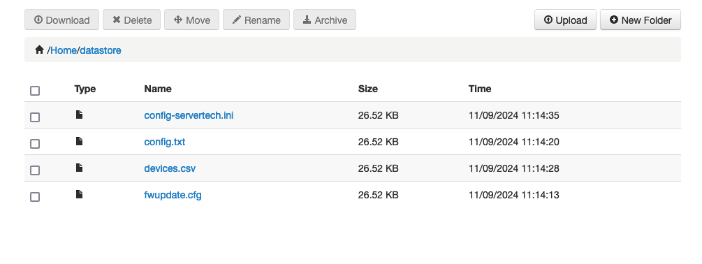
4.2 Upload of files to ZTP Datastore
Now that all configuration files have been created they can be easily uploaded to the datastore which is used for the ZTP process.
In the WebUI navigate to Access.
Click File Manager. This opens a new window with Nodegrid file manager.

Navigate into the datastore folder.
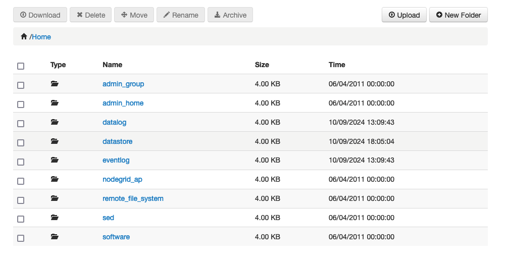
Upload all created files into the datastore folder using the Upload option
5 Start the ZTP Process
After the ZTP (Zero Touch Provisioning) environment is set up, the next step is to provision the Rack PDUs.
All Server Technology PDUs will automatically initiate the Zero Touch Provisioning process when the controller restarts or when the Rack PDU is connected to the network.
To begin, connect the Rack PDU's network interface to the Bold SR netS1 interface and power on the Rack PDU.
The Rack PDU controller will then automatically reach out to the DHCP server to request a new IP address. As part of the DHCP response, the unit will receive the necessary ZTP information. The PDU will download the required files and apply the configuration. Simultaneously, the Nodegrid appliance will detect the Rack PDU and add it as a Managed Device.
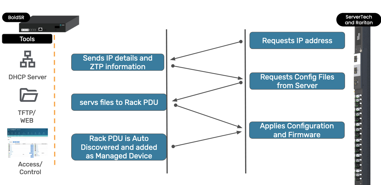
After the Rack PDU is configured, the unit can be accessed via the Nodegrid WebUI and the Outlets can be controlled directly from the Bold SR.
6 Appendix
6.1 Example dhcp.conf file
#Events
on commit {
        set ClientIP = binary-to-ascii(10, 8, ".", leased-address);
        set ClientMac = binary-to-ascii(16, 8, ":", substring(hardware, 1, 6));
        set ClientHost = pick-first-value ( option host-name , "" );
        set ClientVCI = pick-first-value ( option vendor-class-identifier , "" );
        set client_identifier = binary-to-ascii(16, 8, ":", option dhcp-client-identifier);
        execute("/usr/sbin/dhcpd_event.sh", ClientMac, ClientIP, ClientHost);
        execute("/usr/sbin/dhcpd_fixed_address_lease", "--ipv4", "--lease", ClientIP, "--", "hardware_ethernet", ClientMac, "client_identifier", client_identifier, "ClientIP", ClientIP, "vendor-class-identifier", ClientVCI, "client-hostname", ClientHost);
}

option space servertech hash size 3;
option servertech.identifier code 1 = text;
option servertech.ztp-url code 2 = text;

set vendor-string = option vendor-class-identifier;
option space RARITAN code width 1 length width 1 hash size 3;
option RARITAN.pdu-tftp-server code 1 = ip-address;
option RARITAN.pdu-update-control-file code 2 = text;
option RARITAN.pdu-update-magic code 3 = text;
option RARITAN.pdu-model code 4 = text;
option RARITAN.pdu-serial code 5 = text;
option RARITAN.pdu-cascading-info code 6 = text;
option RARITAN.pdu-http-uri-base code 7 = text;
option local-encapsulation code 43 = encapsulate RARITAN;

class "servertech-ztp" {
	match if substring (option vendor-class-identifier, 0, 10) = "ServerTech";
	vendor-option-space servertech;
	option servertech.identifier "STI Params";
	option servertech.ztp-url "tftp://192.168.100.1/datastore/config-servertech-${mac}.ini";
}

class "raritan" {
	match if option vendor-class-identifier = "Raritan PDU 1.0";
	vendor-option-space RARITAN;
	option RARITAN.pdu-tftp-server 192.168.100.1;
	option RARITAN.pdu-update-control-file "fwupdate-${mac}.cfg";
	option RARITAN.pdu-update-magic "20240910-0001";
	option vendor-class-identifier "Raritan PDU 1.0";
}

subnet 192.168.100.0 netmask 255.255.255.0 {
#range low_ip high_ip;
        option domain-name "";
        default-lease-time 86400;
        max-lease-time 86400;
        range 192.168.100.10 192.168.100.200;
}
6.2 Example tftpd file
service tftp
{
        disable         = no
        socket_type     = dgram
        protocol        = udp
        flags           = IPv6
        wait            = yes
        user            = root
        group           = root
        server          = /usr/sbin/in.tftpd
        server_args     = -s /var/opt/tftpboot
}